
Approved Code of Practice - Stretch Tents
GOT Handbook for Stretch Tents
Approved Code of Practice for Stretch Tents and similar structures
Handbook for Stretch Tents
Incorporating the Guild professional framework and the
Approved Code of Practice for the safe erection and use of
stretch tents and similar tensioned membrane structures
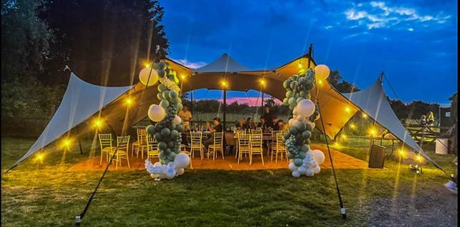
Second edition, August 2026
A not-for-profit professional body. Free handbook, issued in the public interest.
|
Item |
Detail |
|
Title |
The Guild of TentMasters Handbook for Stretch Tents |
|
Structure |
Part One, the Guild professional framework. Part Two, the Approved Code of Practice for Stretch Tents. |
|
Type |
Guild handbook incorporating an Approved Code of Practice (ACOP) |
|
Subject |
Erection of stretch tent structures and similar tensioned membrane structures |
|
Edition |
First edition |
|
Date of issue |
August 2025 |
|
Issued by |
The Guild of TentMasters |
|
Status |
Best-practice guidance. Not a substitute for legal advice. |
|
Review |
To be reviewed periodically and on any material change to law or standards. |
This handbook has two parts. Part One is the Guild of TentMasters professional framework, which explains who the Guild is, why it exists, how competence is recognised, and the command authority that a TentMaster carries. Part Two is the Guild Approved Code of Practice for stretch tents, the technical standard for erecting, using and dismantling these structures safely. The Guild of TentMasters Approved Code of Practice is the ultimate authority for members and for those who adopt it.
The stretch tent has become one of the most versatile structures in the events industry. Its flexible, double-curved membrane can be shaped to almost any site, wrapped around trees and buildings, and joined together to cover large areas. That versatility is also the source of its particular risks. Unlike a framed marquee, a stretch tent has no rigid skeleton. Its shape, its strength and its safety depend entirely on the tension in the fabric and on the integrity of every anchor point. A stretch tent that is correctly rigged is a strong and elegant structure. A stretch tent that is poorly anchored or badly tensioned can fail suddenly and without warning.
This handbook brings together, in one place, the professional standing of the people who put these structures up and the technical standard to which they should work. Part One sets out the Guild framework and the competence and authority that safe work depends on. Part Two sets out the Approved Code of Practice. Throughout, the Approved Code of Practice of the Guild of TentMasters is the governing authority.
This document is a best-practice guide and is not a substitute for legal advice. All work must comply with relevant UK legislation, including the Health and Safety at Work etc. Act 1974.
How to use this handbook
Members and those considering membership should read Part One. Everyone responsible for a stretch tent, from the crew who rig it to the client who uses it, should read Part Two. A reader who wants the essentials only should turn to the plain-language safety summary in Appendix A. Clients and event organisers will find the sections on roles, wind management and emergency procedures the most directly useful.
|
Key to wording: The words must and shall indicate a requirement of law or of this Code. The words should and recommended indicate strong best-practice guidance that should be followed unless there is a good and recorded reason not to. The word may indicates something that is permitted. |
Contents
How to use this handbook.................................................................... 3
The Guild of TentMasters....................................................................... 10
Why join the Guild of TentMasters.......................................................... 10
Origins, purpose and mission............................................................. 10
Industry reaction and momentum....................................................... 11
Why the Guild is needed..................................................................... 11
How to apply for Guild membership.................................................... 11
Membership fees and tiers................................................................. 12
Training courses with the Guild........................................................... 12
Guild chapters and specialisms.......................................................... 12
Member benefits................................................................................ 13
The TentMaster Certificate of Professional Competence......................... 13
For those who work with tensile fabric structures................................ 14
The ESCA Convention and Command Doctrine....................................... 14
Statutory references and further reading................................................ 15
1. Introduction and scope...................................................................... 17
1.2 Scope and application.................................................................. 17
1.3 Status and authority of this Code.................................................. 17
1.4 What is a stretch tent.................................................................... 17
1.5 Legal framework........................................................................... 18
1.6 Relevant standards....................................................................... 18
2. Roles, responsibilities and competence............................................. 19
2.1 Duty holders................................................................................. 19
2.2 Competence and training............................................................. 19
2.3 Supervision.................................................................................. 19
2.4 Choosing a competent hirer or contractor..................................... 19
2.5 Insurance and liability................................................................... 20
2.6 Contracts and handover............................................................... 20
2.7 Legal duties, licensing and permissions......................................... 20
3. Risk assessment and documentation................................................. 21
3.1 Site-specific risk assessment........................................................ 21
3.2 Method statements...................................................................... 21
3.3 On-site documentation................................................................. 21
3.5 Structural calculations................................................................. 22
4. Site selection and preparation............................................................ 22
4.2 Underground and overhead services............................................. 22
4.4 Ground conditions and bearing capacity....................................... 23
4.5 Drainage and flooding................................................................... 24
4.6 Site layout and space planning...................................................... 24
5. The stretch tent fabric and components.............................................. 24
5.1 The membrane............................................................................. 24
5.2 Flame retardancy and certification................................................ 24
5.3 Fabric strength and ageing............................................................ 24
5.4 Poles, clamps, ropes and fittings................................................... 24
5.5 Pre-installation inspection of components.................................... 25
6.3 Soil types and holding power......................................................... 25
6.4 Weight anchors and ballast........................................................... 26
6.5 Ground screws and engineered anchors........................................ 26
6.6 Pull testing and safety factors....................................................... 26
6.7 Double and gang staking............................................................... 26
6.8 Guy-rope angles........................................................................... 26
7.1 Supervision and personal protection............................................. 27
7.2 Manual handling........................................................................... 27
7.3 Working at height.......................................................................... 27
7.4 Layout and pole placement........................................................... 27
7.5 Tensioning and pre-stress............................................................. 28
7.6 The hazard of over-tensioning....................................................... 28
7.7 Pole raising safety........................................................................ 28
7.8 Bracing and stability..................................................................... 28
7.9 Final checks................................................................................. 28
8. Sidewalls, configurations and occupancy........................................... 28
8.1 Sidewall types and fixing............................................................... 28
8.2 Walls on, walls off, and the wind trap............................................ 29
8.3 Occupancy and capacity.............................................................. 29
8.4 Means of escape.......................................................................... 29
8.5 Seating layout and gangways........................................................ 30
8.6 Seating capacity in different countries........................................... 30
9. Wind management plan..................................................................... 30
9.1 Understanding wind..................................................................... 30
9.2 Safe wind speeds and operational limits........................................ 31
9.3 Wind monitoring........................................................................... 31
9.4 Graduated action levels................................................................ 31
9.5 Sidewalls and wind....................................................................... 32
9.6 Ground conditions in adverse weather.......................................... 32
10. Water, snow and weather management............................................ 32
10.2 Rain and ground saturation......................................................... 32
10.3 Snow loads................................................................................ 32
10.5 Joining tents, valleys and condensation....................................... 33
11.1 Fire risk and prevention............................................................... 33
11.2 Flame-retardant materials.......................................................... 33
11.3 Extinguishers and fire points....................................................... 33
11.4 Exits and escape routes.............................................................. 34
11.5 Heating appliances and clearances............................................. 34
11.6 Electrical safety.......................................................................... 34
11.7 Naked flames and pyrotechnics.................................................. 34
11.8 Raising the alarm and fire detection............................................. 34
11.9 Emergency escape lighting and signage....................................... 34
11.10 Separation distances................................................................ 34
12.1 Electrical distribution.................................................................. 35
12.4 First aid and medical provision.................................................... 35
12.5 Welfare facilities......................................................................... 35
13. Inspection, examination and maintenance........................................ 36
13.1 The two-part inspection regime................................................... 36
13.2 Pre-installation inspection.......................................................... 36
13.3 Post-installation inspection and handover................................... 36
13.4 Inspection during use................................................................. 36
13.5 Periodic thorough examination.................................................... 36
13.6 Maintenance, cleaning and storage............................................. 36
13.7 Repairs and modifications.......................................................... 37
14. Dismantling (de-rigging)................................................................... 37
14.1 Supervision................................................................................ 37
14.2 Method statement...................................................................... 37
14.3 Controlled release of tension...................................................... 37
14.4 Working at height and falling objects........................................... 37
14.5 Manual handling......................................................................... 37
14.6 Component care........................................................................ 37
15. Emergency procedures.................................................................... 37
15.1 Emergency plan.......................................................................... 37
15.2 Severe weather evacuation......................................................... 38
15.5 Evacuation and exits................................................................... 38
15.6 Crowd safety.............................................................................. 38
16. Sustainability and environmental protection..................................... 38
16.1 Eco-conscious materials............................................................ 38
16.2 Waste management................................................................... 38
16.3 Pollution and spillage control...................................................... 38
16.4 Energy use.................................................................................. 39
17.1 Documentation platforms........................................................... 39
17.2 Inspection apps.......................................................................... 39
17.3 Alerts and updates..................................................................... 39
18.1 Incident prevention..................................................................... 39
18.2 Efficiency gains.......................................................................... 39
19. Compliance and accessibility........................................................... 39
19.1 Key regulations........................................................................... 39
19.2 Plain language summary............................................................. 39
19.3 Accessibility for all users............................................................ 39
20.1 Safety ownership........................................................................ 40
20.2 Feedback mechanisms............................................................... 40
Appendix A. Plain-language safety summary........................................... 41
Appendix B. Wind action level quick reference........................................ 42
Appendix C. Erection and handover checklist......................................... 43
Appendix D. On-site documentation checklist........................................ 44
Appendix E. Glossary of terms................................................................ 45
Appendix F. Checklist for the assembled structure................................. 46
Appendix G. Sizing the exits, worked example......................................... 47
Appendix H. Relevant legislation and standards...................................... 48
United Kingdom legislation................................................................. 48
EU, UK and USA standards................................................................. 48
Appendix I. Seating capacity in tents, international comparison.............. 49
Appendix J. Fire regulation in tents, international comparison................. 50
Appendix K. Standards by jurisdiction..................................................... 51
Part One
The Guild of TentMasters professional framework
The Guild of TentMasters
The Guild of TentMasters awards qualifications for life and work experience based upon your proven track record. The Guild works on a pan-industry basis in collaboration with ESITS, MUTA, the Events Industry Forum, the Association of Independent Festivals and major employers across the events industry. The Guild is a not-for-profit company limited by guarantee, run by volunteers, whose purpose is to improve standards in an industry where, historically, there were few formal qualifications.

Why join the Guild of TentMasters
Origins, purpose and mission
The temporary structures industry is at a turning point. For decades, expertise in erecting tents, marquees, stages and other temporary demountable structures was passed down through apprenticeship and hands-on experience. Competence was measured by reputation, quality of work and peer recognition, not formal credentials. Today, regulations, European and British technical standards and the Construction (Design and Management) Regulations 2015 require verifiable, documented competence.
The Guild of TentMasters, founded in 1992 to improve standards for the temporary structures industry, now provides a pathway that combines formal assessment and certification with traditional craft knowledge, ensuring tent masters meet modern professional and legal standards. Because of the generosity of trade sponsors, membership has been offered free during the launch period, with modest annual fees expected thereafter.
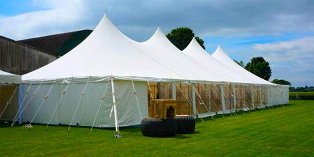
Tent masters have been around for many years. Tenting is among the oldest forms of construction in history, yet there has never been a coherent vocational route for the people who put tents up. Most events fall under CDM 2015, which requires a competent person to sign off a temporary structure. The Guild's role is not to become another trade association, but to act as the professional body that formalises competence where none existed before. It partners with organisations such as ESITS to set course standards and with MUTA to embed this competence within recognised best practice.
The Guild's aims are to promote individuals to become accredited within their specialist field, with their unique type of structure, to embrace ever-evolving compliance, and to act as a forum for advice, knowledge and education for better working practices. Its mission is to prioritise people, practise effectively, preserve safety and promote professionalism, so that the TentMaster title is recognised as a skilled, safety-critical role within the global construction and events industries.
|
A note on terms: A Temporary Demountable Structure (TDS) can be a tent, but many TDS are not tents. A stage without a roof is a TDS, as is a platform, a scaffold, a portacabin or a seating grandstand without a roof. The Guild prefers to call those structures with a membrane element Fabric Roofed Structures, or FRS. When the load-bearing roof membrane is added, the whole dynamic of the structure changes dramatically, as do the forces in the system, so a stage erector without roofing experience may not understand the scale of the increase in loads and forces of the roofed structure. |
Industry reaction and momentum
When formalisation was first proposed in the 1990s, and again in 2012, the idea of certification often met resistance. That perception has shifted. The Guild now sees steady growth, with manufacturers, major contractors and festivals engaging directly. Organisations such as RÖDER, Arena, GL Events and Neptunus are involved in developing standards, and the Guild is partnered with MUTA and active on the Events Industry Forum. For the first time, there is broad acceptance that the sector needs a formal professional framework. In summary, joining the Guild of TentMasters is a strategic investment that offers tent erectors professional development, business growth, personal satisfaction and industry influence.

Why the Guild is needed
Experienced TentMasters have long delivered complex structures safely, but the industry has seen people arrive on site with little understanding of the risks, yet working on structures worth thousands and carrying the public's safety in their hands. High-profile failures have shown the consequences. The people who erect structures now carry all the responsibility but often lack authority. The Guild exists to correct that imbalance by defining competence, linking it to authority, and making it legible to clients, regulators and insurers. Grandfather rights in scaffolding were removed in 2015, and the same change is coming here. The Guild provides an orderly route to a modern standard, formalising the human competence that the technical documents assume.
How to apply for Guild membership
Membership is individual, and all disciplines from design to maintenance are welcome. To apply, complete the online form with your contact details, role and experience, declare your agreement with the code of conduct and with recognised best practice, and submit basic evidence of your experience. Applications are reviewed, and once accepted you are enrolled at the right level and added to the database and public registries.
Membership fees and tiers
Membership is currently free during the launch phase, with modest annual fees, of the order of forty-five pounds, expected later. Members progress through tiers: Tent Geco at entry level, Tent Technician at operational level, and TentMaster as the senior level carrying command authority.

Training courses with the Guild
All Guild training is delivered in partnership with ESITS and MUTA. Courses cover orientation, structure-specific operative and supervisor skills, and Tent Technician level content such as load paths, rigging and weather protocols. The training is aligned with British and European standards and with recognised best-practice guidance, and further e-learning is being brought together in a single online academy.

Guild chapters and specialisms
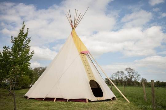
The Guild is organised into chapters covering the main structure types, each with its own tailored code of practice and knowledge sharing. The chapters cover marquees, big tops, frame tents, stretch tents, temporary roofs, Major Event Structures, tipis and manufacturers. This handbook belongs to the stretch tents chapter, and Part Two is its Approved Code of Practice.
Member benefits
Membership brings access to specialist insurance, reduced training rates, Approved Codes of Practice, technical resources, chapters, events and continuing professional development. Members may display the Guild emblem on cards, websites and tenders, are listed on the registry, and gain mentoring, business growth, an enhanced reputation, the ability to command higher rates, professional development, industry influence, wellbeing support, recognition of informal experience, a route into innovation, and the personal pride of belonging to a professional community.
The TentMaster Certificate of Professional Competence
The TentMaster Certificate of Professional Competence, or CPC, is the modern professional successor to historic craft authority. Today's large, complex structures, with public audiences, require more than tenure. They need formal, auditable competence under CDM 2015.
The core benefit is Event Structures Command Authority, or ESCA, and the Master of the Vessel doctrine: unilateral authority over structural safety. A TentMaster's decision to stop work or to evacuate cannot be overruled. This is already reflected in law, through CDM Regulation 8, section 7 of the Health and Safety at Work etc. Act 1974, and Regulation 14 of the Management of Health and Safety at Work Regulations 1999, and it provides command protection, so that fulfilling a legal duty cannot itself result in penalty.
The framework defines the accountable technical role, covering erection methodology, stability, weather decisions, inspection and sign-off. It aligns experience with skills, knowledge, training and experience requirements, offers Level 5 equivalence, and is regulator ready. Requirements include proven experience, leadership, a portfolio, an interview and references. The experience route, currently free, is time limited, after which a full two-stage pathway of practical assessment and technical membrane engineering applies. Holding the CPC opens global networks, demonstrates compliance, protects a career, strengthens tenders, and positions the holder as the recognised Accountable Technical Authority. Professionalisation is inevitable, and applying now secures authority, safety and a future in the industry.
For those who work with tensile fabric structures
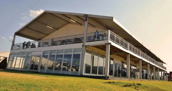
The Guild of TentMasters is a not-for-profit professional standards organisation, training platform and network forum for individual professionals working within the permanent, portable and temporary demountable tensile membrane structure industry. It covers four core objectives: to prioritise individuals, their needs and the sharing of knowledge; to promote safe working practices and sustainability; to produce accredited training courses and qualifications; and to provide expert industry information and awareness.
Individual membership provides access to specialist membrane and TDS courses designed by industry leaders, awareness of BS EN 13782, compliance, engineering and standards, online access to the library, networking and knowledge forum, the annual Guild symposium and member awards, industry supplier discounts, and the confidence to excel in your area of expertise. The community spans architectural tension fabric structures, domes and cable nets, and the PTFE and ETFE elements of buildings and deployable roofs, as well as portable and demountable event structures.
The ESCA Convention and Command Doctrine
The Guild operates under the Event Structures Command Authority, or ESCA, Convention, which defines the legal and ethical framework for structural safety. It establishes clear responsibility, accountability and authority for all involved in temporary structures. Drawing from international safety models such as the Safety of Life at Sea Convention and the International Safety Management Code, the Command Doctrine assigns ultimate responsibility to the designated TentMaster, in the same way that a ship's captain carries ultimate responsibility for the vessel. This ensures that safety decisions prevail over commercial pressures, especially in dynamic conditions such as changing weather or crowd movements. The ESCA Convention is entirely in line with UK law and with the requirements of the Construction (Design and Management) Regulations 2015.


Statutory references and further reading
The Guild framework rests on, and directs members to, the following: the Health and Safety at Work etc. Act 1974; the Construction (Design and Management) Regulations 2015; the Management of Health and Safety at Work Regulations 1999; the Guild standards and Approved Codes of Practice; the ESITS syllabus; recognised industry best-practice guidance; BS EN 13782; and recognised membrane engineering courses. The Guild also welcomes corporate sponsors, and, as it is run by volunteers, its financial requirements are modest.
Approved Code of Practice for Stretch Tents
1. Introduction and scope
1.1 Purpose
This Code of Practice provides guidance for the safe installation of stretch tents and similar tensioned membrane structures in the United Kingdom. It is intended for use by event organisers, hirers, installers, crew, and all those responsible for the health and safety of temporary structures. It also serves the client who takes handover of a completed structure. The purpose is to protect the public, the workforce, and all others who may be affected by the erection, use and dismantling of a stretch tent.
1.2 Scope and application
This Code applies to the design intent, planning, erection, use, inspection and dismantling of stretch tents. The principles also apply to big tops, tipis and other tented structures where the safety of the structure depends on tensioned fabric and on anchorage. Because the integrity of a stretch tent relies on the tension of a flexible membrane rather than on a rigid frame, stretch tents require specific procedures that differ from those for traditional marquees and frame tents. This document should always be used together with the manufacturer's specific instructions for the structure being erected. It applies to short-term hire; long-term or semi-permanent installations may bring further duties.
This Code is a best-practice guide and is not a substitute for UK law. All operations must comply with the Health and Safety at Work etc. Act 1974 and its associated regulations. The erection and dismantling of structures at events is construction work within the meaning of the Construction (Design and Management) Regulations 2015.
1.3 Status and authority of this Code
This document is the Approved Code of Practice of the Guild of TentMasters for stretch tents. It draws on the accepted good practice of the wider events industry and on published EU, UK and USA standards. Where those sources differ in detail, or where they are silent, this Approved Code of Practice is the ultimate authority for members of the Guild and for those who adopt it. Following this Code does not remove the duty of every party to comply with all relevant legislation, nor does it replace the manufacturer's instructions for a particular structure.
1.4 What is a stretch tent
A stretch tent is a structure formed from a single, highly elastic technical fabric that is anchored at its corners and along its sides and then pushed up from beneath by poles to create peaks and valleys. There is no internal frame. The fabric itself is the structure. This gives four defining characteristics that govern everything in this Code:
• The fabric carries the load. Any tear, weak seam or failed clamp can affect the whole structure, so the condition of the membrane and its connections is safety critical.
• Tension is everything. The structure is only stable, and only sheds water and wind correctly, when the fabric is taut and evenly tensioned. Slack areas invite water pooling and uncontrolled flapping.
• Anchorage is everything. With no frame to stand on, the structure depends entirely on a large number of anchor points. The ground must be able to hold them.
• It is a temporary structure, not a building. A stretch tent does not have the wind and snow capacity of a permanent building and must never be treated as though it does.
Not all fabrics are equal. A stretch tent must use a properly water-resistant and flame-resistant technical fabric. Before hire, confirm that the fabric will not let water in and will not readily catch fire, and that certification is available (see Section 5).
1.5 Legal framework
The erection and use of a stretch tent is work, and the full weight of health and safety law applies. The principal duties arise under, but are not limited to, the following:
• Health and Safety at Work etc. Act 1974, the overarching duty to protect employees and others.
• Management of Health and Safety at Work Regulations 1999, requiring risk assessment and safe systems of work.
• Construction (Design and Management) Regulations 2015, under which the event organiser normally carries the client duties and is responsible for ensuring a comprehensive safety file and plan is produced for the event.
• Work at Height Regulations 2005.
• Manual Handling Operations Regulations 1992.
• Provision and Use of Work Equipment Regulations 1998.
• Lifting Operations and Lifting Equipment Regulations 1998.
• Personal Protective Equipment at Work Regulations.
• Control of Substances Hazardous to Health Regulations 2002.
• Electricity at Work Regulations 1989.
• Regulatory Reform (Fire Safety) Order 2005, under which the responsible person for the event must carry out a fire risk assessment.
• Reporting of Injuries, Diseases and Dangerous Occurrences Regulations 2013 (see Section 21).
|
Duty of care: The event organiser and the hirer both hold duties under health and safety law, to a degree that depends on how much control each has over the work. The extent of control should be agreed and recorded in the contract. |
1.6 Relevant standards
This Code is consistent with the following published standards, cited here as EU, UK and USA standards, which readers may consult for detailed technical requirements. Where a structure is used outside the United Kingdom, the standards and codes of the country of use apply as well, and a jurisdiction-by-jurisdiction map is given in Appendix K[1,2,3,4,5]. Full details of every source cited in this handbook are listed, with links, in the References at the end.
|
Standard |
Region |
Subject |
|
BS EN 13782 |
EU / UK |
Temporary structures. Tents. Safety. The core standard for tent design, calculation, manufacture, installation, examination and use. |
|
BS EN 17879 |
EU / UK |
Event structures. Safety requirements. Operational and design wind states, wind management plans and ground conditions. |
|
CEN/TS 19102 |
EU |
Design of tensioned membrane structures. Engineering design of fabrics, foils, connections and prestress. |
|
EN 15619 |
EU |
Rubber or plastics coated fabrics for tents. Fabric performance and declaration. |
|
BS EN 1991-1-4 |
EU / UK |
Actions on structures. Wind actions. The basis for wind loading. |
|
BS EN 12811-1; BS 5975 |
EU / UK |
Temporary works equipment and falsework, where platforms or scaffolding support a structure. |
|
BS 7837; BS 5438; BS 5867; BS 476-7 |
UK |
Fire performance and flame propagation testing of membranes, fabrics, linings and surface spread of flame. |
|
BS EN 1125; BS EN 179 |
EU / UK |
Panic and emergency exit hardware. |
|
NFPA 701; IBC; ASTM |
USA |
Flame propagation testing of fabrics, model building code provisions for tents, and materials test methods. |
2. Roles, responsibilities and competence
2.1 Duty holders
Safety on a stretch tent job is shared, but the responsibility of each party must be clear. As a general guide:
• The event organiser, normally the client under CDM 2015, is legally responsible for ensuring that a comprehensive safety file and plan is produced for the event, and for co-ordinating the various contractors on site.
• The hirer or installer is responsible for supplying a structure that is fit for purpose, for erecting and dismantling it safely, and for handing it over in a safe condition with the correct documentation.
• The client or user takes on responsibility for the structure once it has been handed over, in particular for monitoring the weather and calling for help when conditions change (see Section 9).
• Every worker has a duty to take reasonable care for their own safety and for the safety of others affected by their work, and to follow the safe systems of work that have been put in place.
2.2 Competence and training
All personnel involved in the installation must be competent and appropriately trained for the specific type of structure they are working on. For a stretch tent this is not the same as general marquee experience. Crew must understand how the fabric behaves under tension, how tension is built and released in the correct sequence, and how the structure responds to wind. Competence includes an understanding of the manufacturer's instructions, the risk assessment, and safe working practices.
Competence should be capable of being evidenced. Acceptable evidence includes records of relevant training, records of supervised experience on this type of structure, a recognised competency or skills card, and recognised qualifications such as an appropriate vocational qualification in temporary structures. Full-time crew should refresh their site-safety training periodically, of the order of every five years, and all crew should receive a basic on-site health and safety induction. At least one member of each crew should hold current first-aid training, with documentation. Training records should be kept and made available on request.
2.3 Supervision
Every installation and every dismantle must be supervised by a competent person who has a thorough understanding of the manufacturer's rigging manual and of the specific risks associated with the site. During critical operations, in particular the raising of poles and the release of tension, there must be one clear voice giving instructions so that the crew act together. Mechanical equipment such as vehicles, forklifts, telehandlers and access equipment must be operated only by trained and, where required, licensed persons.
2.4 Choosing a competent hirer or contractor
An event organiser has a duty of care to workers and to the public and must choose a competent contractor. Competence can be judged, and evidenced, by looking at the following:
• Experience and track record. How long the contractor has traded, the number and size of similar structures they have handled, and references from past customers.
• Financial standing. A stable business is better able to hold spare equipment and crew for contingencies. Be cautious of unusually low prices or of large discounts offered for big early deposits, which can be a sign of financial trouble.
• Range and suitability of equipment. Whether the equipment offered is fit for purpose and comes with fire and structural documentation.
• Resources for contingencies. Spare equipment, standby staff and transport for last-minute or emergency situations, and an agreed out-of-hours emergency contact number and response time.
• Knowledge of current health and safety requirements, and the ability to monitor and respond to changing weather.
• Membership of a recognised professional body or trade association and adherence to a published code of practice. This handbook is issued for that purpose.
2.5 Insurance and liability
A competent contractor must carry adequate public liability insurance, and, where relevant, product liability insurance. Public liability cover of at least one million pounds is regarded as a minimum, and larger events will require more. In addition, any business with employees must by law hold employers' liability insurance, for which the statutory minimum cover is five million pounds. The organiser should ask to see current certificates of insurance and confirm that the cover is appropriate to the size of the event. Proof of insurance is one of the documents that should be requested before any contract is signed.
2.6 Contracts and handover
Work should proceed under a signed contract, typically a booking form together with terms and conditions of hire. A reputable contractor will insist on this. The contract should make clear who is responsible for what, especially the monitoring of the structure and the weather during the event, and should define the areas of responsibility of each party. On completion of the erection, the contractor should carry out the final safety checks, complete the sign-off documentation, and formally hand over the structure as safe to use. A responsible person from the client should be present at handover for the positioning, the formal handover and an inventory check. After handover, no client or third party should modify the bracing, anchorage or exits; only the contractor should do so.
|
Documents to request before hire: safety policy; risk assessments; method statements; construction phase plan where CDM requires one; training, competency and skills-card records; proof of public liability and employers' liability insurance; structural calculations stating the maximum approved wind loading and imposed load; flame-retardancy (fire) certificates; wind management plan; and itemised quotation with contract terms. |
2.7 Legal duties, licensing and permissions
The erection and dismantling of a stretch tent at an event is construction work under the Construction (Design and Management) Regulations 2015[16]. On any project involving more than one contractor, the duty holders must be appointed and their roles understood: the client, normally the event organiser, who makes the suitable arrangements and provides information; the principal designer, who plans and co-ordinates health and safety in the pre-construction phase; and the principal contractor, who plans, manages and co-ordinates the build and the dismantle. Larger or longer projects may require notification to the enforcing authority. Everyone on site must co-operate, co-ordinate and communicate.
Separate permissions may also be needed. Where the event involves licensable activities such as the sale of alcohol or regulated entertainment, it must be covered either by a premises licence or, for a small event, by a Temporary Event Notice under the Licensing Act 2003[18]. A Temporary Event Notice is limited in the number of people, the duration and the number of events per year. Planning permission and building control may apply to larger, enclosed or longer-standing structures. For qualifying public events, the organiser should also consider counter-terrorism protective-security duties. These permissions sit alongside, and do not replace, the health and safety duties in this Code.
3. Risk assessment and documentation
3.1 Site-specific risk assessment
A site-specific risk assessment must be completed before any work begins. A generic risk assessment is not enough on its own. It must identify the potential hazards and set out the controls. For a stretch tent it must pay special attention to:
• Wind exposure of the site and the wind rating of the structure.
• Ground conditions and the suitability of the ground for a large number of anchor points.
• Underground services, overhead power lines and other overhead obstructions.
• The potential for water pooling (ponding) on the fabric.
• The management of tensioned ropes and the trip hazards they create around the perimeter.
• Working at height, manual handling, lifting operations, transport and moving vehicles, electricity and fire, and the safety of the public and other site users.
3.2 Method statements
A method statement should set out the safe sequence of work for both the erection and the dismantling of the structure. For dismantling in particular, the method statement should identify the hazards and the correct order in which tension is to be released. The method statement should be understood by the whole crew before work starts, usually through a short briefing at the start of the job.
3.3 On-site documentation
All relevant documentation must be available on site, including:
• A copy of this Code of Practice.
• The manufacturer's specific manual for the stretch tent model.
• The site-specific risk assessment and method statements.
• A plan of the site showing the location of the structure.
• Details of the anchorage system used.
• The site-specific emergency plan.
• The wind management plan.
• Structural calculations for the configuration in use.
• Flame-retardancy (fire) certificates for the fabric and other materials.
• The health and safety policy, competency and skills-card records, and proof of public liability insurance, available on request.
3.4 The tent log
Each structure should have a tent log, sometimes called a tent book, that travels with it and is available on every erection site as a record of its history. The log should contain the design and operating data for the structure, the construction and static information, and instructions for erection, dismantling, maintenance and repair. It should also record the results of examinations and any repairs or modifications, and a list of the parts that require periodic replacement. Keeping the log up to date is the simplest way to demonstrate that a structure has been properly looked after.
3.5 Structural calculations
Structural calculations demonstrate that the structure, its anchorage and its ground bearing can withstand the loads expected at the site, in particular wind. For larger or complex structures, or where the fabric is relied on for strength or stiffness, the calculations should be prepared or verified by a qualified structural engineer, and a complex structure may need an independent check by a competent person. The calculations must state the maximum wind loading approved and the maximum imposed load. Where advertising banners, scrim or any additional surfaces are to be attached, these change the wind loading and must be included in the structural assessment. Any such change should be subject to an independent design check and to change control, so that a modification made for appearance does not quietly reduce the safety margin of the structure.
4. Site selection and preparation
4.1 Site suitability
The chosen site must be suitable for the structure. The ground should be as level and stable as possible and free from obstructions. The site must be large enough to accommodate the footprint of the tent plus the additional space required for the angled guy ropes, which for a stretch tent extend well beyond the edge of the fabric. Consideration must be given to the orientation of the structure relative to the prevailing wind, and to the distance from buildings, vegetation and other structures for reasons of both wind and fire spread. As a guide, allow at least six metres between separate fabric structures. Grass and vegetation within the footprint, the working area and the access route should be cut and the clippings removed, and the site should be kept clear of accumulating rubbish, which must not be allowed to gather under platforms.
4.2 Underground and overhead services
Underground services must be identified by the client and clearly marked before any ground penetration. Where there is any doubt, a cable avoidance tool (CAT) or similar device must be used to scan the entire anchor point area to locate and avoid buried services before stakes or anchors are driven. Underground services to consider include electrical cables, gas, water, telephone, drainage and septic runs, sprinkler and irrigation lines and swimming pool pipework.
Overhead power lines are a particular threat, because electricity can arc across a gap from high-voltage lines. Working within six metres of overhead power lines should be avoided. Where work near overhead lines is unavoidable, the minimum clearances below must be maintained, and the line owner should be contacted about shrouding or isolation. The structure must never be installed directly under or near overhead power lines, and a safe working distance must be maintained at all times, including when poles are being raised. Overhead telephone lines and overhanging tree branches must also be identified and allowed for.
|
Plant near overhead lines: Where vehicles, cranes or access equipment work near overhead lines, greater exclusion distances apply, and physical barriers or goal posts should be used. Take advice from the line owner before work begins. |
4.3 Access
The site must have suitable access for vehicles and equipment, including for any mechanical handling plant or access equipment that the job requires. Stretch tents involve large, heavy rolls of fabric and long poles, so access and a safe area for unloading should be confirmed in advance. Where mechanical plant such as forklifts or telehandlers will be used, the contractor should inform the organiser and a safe system of work should be agreed. Emergency vehicle access must also be planned: a fire appliance should be able to reach to within about fifty metres of any part of the structure, along routes not less than about four metres wide with no overhead structure or cable lower than about four and a half metres, and firm enough to carry the weight of a fire appliance in all weathers.
4.4 Ground conditions and bearing capacity
The ground must do two things at once: it must hold the anchors against uplift and sideways pull, and it must carry the downward load under the poles without the poles sinking or the ground settling unevenly. The integrity of a stretch tent is entirely dependent on its anchor points, so the ground must provide excellent anchor holding. If the ground is soft, sandy or otherwise unstable, the number of stakes must be increased, or an alternative engineered anchoring system such as ground screws or concrete blocks must be used as specified by a competent person or structural engineer. If in doubt about the ground, a structural engineer should be consulted.
Poles bear on the ground through base plates. On soft ground the base plates should sit on timber spreaders such as scaffold boards, sized to spread the load. Wet or rotten timber must not be used. The table below gives indicative allowable bearing pressures for short-term temporary use as a guide only. The actual bearing capacity must be judged on site by a competent person, and a conservative value should be used where there is no site-specific data.
|
Ground type |
Indicative allowable bearing pressure |
|
Dense sand and gravel |
up to about 200 kN/m2 |
|
Medium dense sand and gravel |
about 150 kN/m2 |
|
Loose sand and gravel |
about 75 kN/m2 |
|
Stiff clay |
about 150 kN/m2 |
|
Firm clay |
about 75 kN/m2 |
|
Made ground, peat or organic soils |
not to be relied on without expert assessment |
|
No site-specific data available |
use a conservative value, of the order of 50 kN/m2 or less |
|
Uneven and sloping ground: Avoid excessive packing under bases. Where the ground level varies by more than about 0.75 m across the footprint, use engineered platforms or scaffolding and give special attention to the anchorage. Any platform or scaffold grid that supports the structure must comply with the relevant temporary works standards, and the supplier should certify this in writing. Timber spreaders may be used on grass only where the topsoil layer is shallow, of the order of 250 mm or less, and the ground is dry and stable. |
4.5 Drainage and flooding
Avoid sites where surface water can soften, erode or scour the ground around the anchors. Consider where rainwater will run and ensure that any downpipes or run-off discharge away from the supports and anchors. Frame and tension structures can sink into the ground when it floods, even lightly, and under severe waterlogging the soil can behave almost as a fluid, greatly reducing the holding power of anchors and the bearing of foundations. Sites with voids, basements or drains beneath the intended footprint require particular care.
4.6 Site layout and space planning
The internal layout affects both comfort and safety. As a planning guide, allow sufficient area per guest for the intended use, remembering that furniture, staging, dance floors and bars all reduce the usable area. As a rule of thumb for stability and to avoid a tunnel effect, keep the length of a structure to no more than about three times its width. Crucially, the layout of furniture must always keep the fire escape routes and exits clear and must not obstruct the emergency exits (see Sections 8 and 11).
5. The stretch tent fabric and components
5.1 The membrane
The membrane is the structure. A stretch tent must use a purpose-made, highly elastic technical fabric, typically a coated polyester or similar engineered textile, that is designed to be tensioned into a double-curved form. The fabric must be genuinely water resistant, so that it sheds rain rather than absorbing it or letting it through, and it must retain its elasticity and strength across the range of temperatures and humidity it will meet in service. Coated fabrics should be supplied with a supplier's declaration or certificate of their performance.
5.2 Flame retardancy and certification
The fabric, together with any walls, linings, drapes and decorative materials, must be flame retardant to a recognised standard, and the certification must be available on site. Membranes and fabrics should be inherently or durably flame retarded and tested to the relevant UK and EU fire-performance standards; linings and drapes and other sheet materials have their own applicable standards. The material must not readily support combustion and must not produce flaming molten droplets, and every panel should be permanently labelled to show its flame-retardant performance. Flame propagation and ignition performance are also tested to recognised USA methods. A stretch tent fabric that cannot be shown to be flame retardant must not be used for public events. Ask specifically for the fire certificate and check that it matches the fabric supplied.
5.3 Fabric strength and ageing
Technical fabrics lose strength with age, ultraviolet exposure and repeated folding. As a general guide drawn from the relevant standards, a coated polyester fabric should retain at least about seventy per cent of its original tensile strength after several years of service, and fabrics that fall below this should be withdrawn from load-bearing use. Repeated creasing along the same fold lines is a known cause of local weakening, so fabrics should be packed and stored to avoid sharp permanent creases. Roof and wall covers should be checked for tears and repaired before reuse.
5.4 Poles, clamps, ropes and fittings
Every component in the load path matters. Poles must be straight, undamaged and of the correct type for the configuration. Clamps, carabiners, shackles and other connectors must be free of defects and of adequate rated strength. Ropes, whether natural or synthetic, must be of the correct type and diameter and used within their safe working load, which is a fraction of their breaking strength; any rope with more than about twenty per cent fraying must be discarded. Wire ropes should be checked for fraying and for the integrity of thimble loops. Ratchets and tensioners must be sound and secured against accidental release. Open hooks must not be used in wind bracings or in any safety-critical connection; hooks with a safety catch should be used instead. Where timber poles are used, shrinkage splits are acceptable only where the total depth of the splits at any point around the pole is no more than half the diameter of the pole.
5.5 Pre-installation inspection of components
Before rigging, all components of the structure must be inspected to ensure they are in good condition and free from damage. Inspect the fabric membrane for any tears, holes, weak seams or damaged weld lines. Check all clamps, carabiners, grommets, webbing, ropes and cables for wear, fraying, corrosion or fatigue. Ensure all poles are straight and undamaged. Any component in doubt must be repaired or replaced before it is used, not after.
6. Anchorage
6.1 Principles
All structures must be adequately anchored to resist wind loads. For a stretch tent the anchorage is not a detail, it is the structure's connection to the earth and the single most important safety element. The anchorage system must be designed to withstand the maximum expected wind speeds for the location and must be sufficient for the maximum uplift. Every anchor point, including every intermediate one, must be secured. Wind changes the shape of the tent and loads the anchors, and trapped rainwater (ponding) can build forces that exceed the capacity of individual stakes. The whole anchorage must therefore be considered as a system, with an adequate margin of safety.
6.2 Stakes
Where stakes are used they must be of a suitable length and diameter for the ground conditions. The holding power of a stake increases with its diameter, with its depth, and with the quality of the soil, and decreases as the soil becomes wetter. Stakes should be driven so that they resist the pull of the guy rope efficiently, with the rope attachment kept low, of the order of a few centimetres above the ground, to reduce leverage and creep. As an absolute minimum, each upright should be held by at least one stake not less than 450 mm long and 12 mm in diameter, driven fully into firm ground, and more or larger stakes will usually be needed. As a further guide from the relevant standards, a driven rod anchor typically needs a minimum embedded depth of the order of 800 mm to develop reliable capacity, subject to the ground and to testing. Purpose-designed stakes with defined heads and eyes are preferred, and projecting stake heads should be padded.
|
Stretch tent practice: In firm ground a common working peg for a stretch tent is of the order of 25 mm diameter and 1000 mm long. In soft or sandy ground use longer pegs, of the order of 1500 mm, and add a second or third peg where a single peg drives in too easily. As a rule of thumb, the distance of the peg from the edge of the fabric should be about the same as the height of the pole it serves, and side poles are commonly leaned out at about 15 degrees once the fabric is tensioned. |
6.3 Soil types and holding power
Holding power varies enormously with soil type. The crew must be able to recognise the ground they are working in and adjust the anchoring accordingly. The following broad classifications are used to judge holding capacity:
• Sand and gravel, stiff clay and hardpan: generally good holding when dry and undisturbed.
• Soft clay, loam and silts: moderate to poor holding, requiring longer or additional anchors.
• Organic, made or filled ground and waterlogged soil: unreliable, requiring engineered anchors or ballast.
Two failure modes must be guarded against: pull-out, where the stake slides out of the ground, and sideways soil failure, where the soil in front of the stake yields and bulges. Both are made worse by wet ground and by loose, non-cohesive soils, which give the least resistance and may require special anchors and pull-out tests.
6.4 Weight anchors and ballast
Where the ground cannot be staked, or as a designed alternative, the structure may be held down by ballast such as water ballast or concrete blocks. Ballast must be calculated, with a safety factor, and be of sufficient weight to provide the required resistance to overturning, sliding and uplift; the weight required is often underestimated and can amount to several tonnes per point. As an indicative starting point drawn from manufacturer guidance, a stretch tent that cannot be staked may need ballast of the order of 600 kg at each corner anchor and 300 kg at each side anchor, but the actual figures must come from the structural design for the specific tent, span and wind rating. It must be connected to the structure in a way that reliably transmits the load. An integral timber floor contributes little to holding down, mainly at its outer edge, and should not be relied on as ballast. Loose furniture or incidental weights must never be relied upon as ballast unless they are properly secured and their restraint is assured.
6.5 Ground screws and engineered anchors
On difficult ground, engineered anchors such as ground screws, helical anchors, folding or wing anchors, or purpose-designed anchor systems may be specified by a competent person. Special anchors of this kind should be load tested to establish their capacity, with an adequate safety factor applied to the lowest result of the tests.
6.6 Pull testing and safety factors
Where there is any doubt about the ground, the holding capacity of the anchors should be confirmed by pull testing on the actual site, because published values are only a starting point. Testing is best done with a calibrated load cell and a suitable pulling device at several locations around the anchor line, with the results recorded. A safety factor is then applied so that the working load on an anchor is only a fraction of the load at which it would fail. The events industry commonly works to a safety factor of the order of 1.5 to 2.0 on staking, and a higher factor should be used where the subsurface conditions are uncertain. When friction between a base and the ground is combined with soil anchors, the friction contribution is usually discounted, to about seventy per cent, because vibration can loosen the contact.
6.7 Double and gang staking
Where a single stake cannot develop the required capacity, additional stakes can be used together. In double staking a second stake is placed behind the first to support it; as a rule of thumb the spacing between them is related to the depth of the stake. In gang staking several stakes are linked through a rigid plate or yoke so that they share the load evenly. As wind design criteria rise, multiple and gang staking become more common. The number of anchor points on a stretch tent is typically high, and on high-load designs it will be higher still.
6.8 Guy-rope angles
The angle of the guy rope to the ground affects both the holding power of the anchor and the balance of forces in the structure. Anchors are commonly placed at a distance from the structure of the order of three quarters of the eave or upright height, and a pull angle in the region of 45 degrees is often used to balance the vertical and lateral components of the load. The correct placement for a given stretch tent is set by the manufacturer's design, which specifies where the fabric is pulled and at what angle, and this must be followed.
7. Installation (rigging)
7.1 Supervision and personal protection
The rigging process must be supervised by a competent person with a thorough understanding of the manufacturer's rigging manual and of the site-specific risks. The supervisor should confirm that the risk assessment and method statement have been briefed, that the ground and services have been checked, and that all components have passed pre-installation inspection before work begins. No members of the public should be admitted during erection or dismantling until the structure is complete and safe.
Suitable personal protective equipment must be available and used. Protective footwear should be worn at all times. Head protection should be worn where there is overhead work, including on adjacent sites, or where wind could dislodge overhead components such as purlins before or after roof sheets are in place. High-visibility clothing should be worn where there is a risk from moving vehicles or where large components are being handled. Gloves, eye protection, sun protection and, where appropriate, harnesses should be provided. Hearing protection must be worn where stakes are driven by a pneumatic hammer, and the task should be rotated among the crew.
7.2 Manual handling
All manual handling operations must be risk-assessed and carried out in accordance with the Manual Handling Operations Regulations 1992. Stretch tent fabric rolls and poles are heavy and awkward, so mechanical aids should be used wherever possible and team lifts should be planned and led by one person.
7.3 Working at height
All work at height must be carried out in accordance with the Work at Height Regulations 2005, following the hierarchy of, first, avoiding work at height where possible, second, using equipment or measures that prevent a fall, and third, using equipment that minimises the distance and consequences of a fall. Collective measures, such as a boarded platform or safety nets, take priority over personal measures such as harnesses. Use a suitable and safe working platform such as a scaffold tower or a mobile elevating work platform where work cannot be done safely from the ground, and plan in advance how a person would be rescued from height. Work at height should stop when the weather makes it unsafe; as a guide, work at height on the structure should cease once gusts reach the order of 12 metres per second.
7.4 Layout and pole placement
Lay out the fabric membrane flat on the ground, on a clean surface and, where necessary, on a protective ground sheet with any sharp objects removed. Position the king poles and side poles according to the manufacturer's layout diagram for the configuration required, for example all sides up or one side down. Take care not to overpull the fabric during layout.
|
Pole geometry and safety straps: For a freeform stretch tent, centre poles are commonly spaced of the order of 4.5 to 6 metres apart, following the manufacturer's layout. Every pole tip should carry a spreader plate or protective cap so that it spreads the point load into the fabric and cannot punch through. Where the design provides safety straps, they should run in the valleys between the rows of centre poles, giving a secondary load path should a pole or fixing fail. |
7.5 Tensioning and pre-stress
Tension is what makes a stretch tent a structure. Attach the ropes to the clamps on the perimeter of the tent and secure the initial anchor points. The sequence in which the anchors are secured and tensioned is critical and must follow the manufacturer's instructions, so that tension is built up evenly across the membrane. Raise the king poles first, followed by the side poles, progressively tensioning the structure as the poles go up. On soft ground use blocks, pads or footings under the poles. The tent should be tensioned until the fabric is taut and smooth, with no visible sagging and no slack areas, because slack areas lead to water pooling and to uncontrolled flapping in the wind.
The membrane is pre-stressed deliberately to stabilise it against wind and to prevent it from whipping or fluttering. The permanent working tension at the edge of the membrane is only a small fraction of the fabric's short-term strength, so that there is a large reserve for gusts and other loads.
7.6 The hazard of over-tensioning
|
Warning: Over-tensioning is a real danger. Pulling the fabric too tight can flatten the roof so that it no longer sheds water and instead collects it, can distort the intended shape and alter the way loads flow, and can tear the fabric or webbing and cause the structure to collapse. Tension to the manufacturer's specification, not beyond it. |
7.7 Pole raising safety
The raising of poles is one of the most hazardous moments of the job. A falling pole can cause serious injury. Poles must be raised in a controlled manner, with the crew briefed, one clear voice giving the commands, and everyone clear of the fall zone. The structure should be secured to its anchorage before large surfaces are raised, so that a partly raised tent cannot act like a sail or a kite in a gust. Where the design uses tall poles or wide spans, poles and masts should be independently guyed or guided so that a partial failure of the membrane does not immediately bring them down.
7.8 Bracing and stability
Where a structure relies on bracing in the roof and walls, the bracing must be installed as the manufacturer specifies, correctly positioned and adequately tensioned. As a general pattern, bracing is provided in the end bays and at intervals along the structure, with intermediate bracing where a run continues beyond several bays. All locking pins and bolts must be secure and eave connection joints locked home.
7.9 Final checks
Once rigged, conduct a full inspection before the structure is handed over. Check every clamp and every anchor point. Ensure all poles are vertical and correctly seated on their base plates. Check the membrane for even tension across the whole surface, with no visible sagging and no slack pockets. Confirm that guy ropes are tensioned, that exposed ropes and stakes near exits and walkways are marked or roped off, and that the emergency exits are clear and correctly formed.
8. Sidewalls, configurations and occupancy
8.1 Sidewall types and fixing
Sidewalls may be solid (opaque), clear (window) or mesh, and all must comply with the applicable fire requirements. Walls are typically hung from the eave line and fixed uniformly, with sections overlapped. Where walls are anchored down at the base by staking, weight, cabling or a baseboard, the fixing must not obstruct the means of escape, and the number and width of exits must still meet the requirements for the occupancy. Walls should be pegged or secured, and a roof lining must not be allowed to drop below the eaves.
8.2 Walls on, walls off, and the wind trap
Most stretch tents are designed to be used either with the walls completely on or completely off. If only part of the structure is walled, there is a danger of creating a wind trap, in which wind entering the structure cannot escape and internal pressures rise to a dangerous level. In high winds the sides of a temporary structure must be either completely open or, preferably, completely shut. Raising or lowering the sides of a non-standard structure such as a stretch tent should be done only by the contractor, and if the sides are to be left raised the contractor must have active systems to assess the wind continuously and to send staff to lower the sides when needed. Sidewalls also change the wind behaviour of the structure, tending to increase uplift on the downwind side and around the perimeter, which increases the load on the anchors.
8.3 Occupancy and capacity
The safe capacity of a structure is set by the available floor area, the layout, and above all by the means of escape. Where there is no fixed seating, the capacity is estimated from the floor area available to the public, excluding areas such as toilets and stairways, divided by an occupant load factor for the type of use. Indicative occupant load factors are given below. Bench seating is counted by dividing the total length of the bench by about 450 mm per person, and fixed seating by the number of seats. Where a space has more than one possible use, the most onerous factor should be used. The final capacity must never exceed what the exits can safely discharge (see Section 8.4 and Appendix G).
|
Type of use |
Floor area per person |
|
Standing spectators, close-packed assembly, dance floor, queuing |
about 0.3 to 0.5 m2 per person |
|
Bar areas |
about 0.3 to 0.5 m2 per person |
|
Conference, dining, restaurant seating |
about 1.0 to 1.5 m2 per person |
|
Lounge, common room, waiting area |
about 1.0 m2 per person |
8.4 Means of escape
Every enclosed structure must have a safe means of escape. Drawing on the relevant standards, the following principles apply and should be read together with the fire safety requirements in Section 11 and the exit calculation in Appendix G:
• Any structure holding more than 50 persons must have at least two exits, well separated and evenly distributed so that a single incident cannot block them all, with at least one suitable for wheelchair users.
• Emergency exits should be at least 2.0 m high and at least 1.0 m wide. Exit width is counted in units, where one unit is about 525 mm and discharges about 40 persons per minute, and the aim is to clear the structure within about two minutes.
• Travel distance to a final exit should normally not exceed about 24 m; a ramp or stairway adds about 0.25 m to the travel distance for each 1 m of its length.
• Doors on exit routes must open outwards in the direction of escape, be easy to open from the inside, and where secured be fitted with panic or emergency exit hardware to the relevant standards. Fabric flap exits must be quick-release.
• Exits must be clearly signed, with white-on-green signage to the relevant standard, visible by day and by night, inside and outside. When calculating exits, assume that one exit may be unavailable in an emergency.
• Publicly accessible stages or platforms more than about 600 mm high should be fitted with a guardrail at least 1 m high, and public ramps should have a gradient no steeper than about 1 in 12 with a non-slip surface.
8.5 Seating layout and gangways
How the seats are arranged is as important to safety as how many there are. Loose chairs used in rows for an audience should be secured together in lengths, for example battened or clipped into rigid blocks, so that they cannot be scattered into an escape route in a hurry. The following planning rules, drawn from the relevant standards, keep seated audiences safe:
• Rows should have a clear seatway between them, measured between the back of one seat and the front of the seat behind, of at least about 300 mm, increasing to about 400 to 500 mm for longer rows.
• Limit the number of seats in a row before a gangway is reached: as a guide, no more than about 7 seats where there is a gangway at one end only, and no more than about 14 seats where there are gangways at both ends, increasing only where the seatway is widened accordingly.
• Gangways and aisles serving seating should be at least about 1.05 m wide, kept clear, and should not taper or end in a dead end.
• Fixed or ganged seating is counted seat by seat; loose seating and standing areas are counted by the occupant load factors in Section 8.3 and Appendix G.
• Provide clearly identified spaces for wheelchair users on the level, near an accessible exit, without blocking the escape route for others.
8.6 Seating capacity in different countries
The method of setting a safe capacity differs from country to country, and the standard of the country of use governs. In outline: the United Kingdom uses floor-space factors and units of exit width of 525 mm discharging about 40 persons per minute[10,11]; several European countries, following the German model, set escape-route width at about 1.20 m for every 200 persons indoors and limit rows to about 30 seats[1]; the United States uses net floor area per person, about 7 square feet for closely seated chairs, 5 for standing and 15 for tables and chairs, with egress width of about 0.2 inches per person and aisles at least 44 inches wide[25,26]; and Australia sets the number of exits in bands by occupancy and uses about 0.5 square metres per person for standing areas[27,28]. A side-by-side comparison is given in Appendix I, and the worked exit calculation in Appendix G.
9. Wind management plan
Compliance with the standards, guidelines and historical data in this Code all underpin the commitment of the TentMaster to providing a safe and well installed structure for the client. However, once the structure has been handed over to the client, the TentMaster becomes the client's partner in handling the potential for bad weather, because the crew will no longer be on site. This section sets out simple guidelines and an action plan. It applies during build, during the event and during dismantling.
9.1 Understanding wind
Wind is unpredictable and is one of the greatest hazards to a temporary structure. Wind pressure rises with the square of the wind speed, so a modest increase in speed produces a large increase in load. A rise from 12 to 17 metres per second roughly doubles the pressure, and a rise from 12 to about 24 metres per second roughly quadruples it. This is why action must be taken early, well before conditions look dangerous.
9.2 Safe wind speeds and operational limits
It is current practice for the event industry to vacate a structure when wind speeds reach 28 metres per second, or 60 miles per hour. At that point neither the public, the tent crew, other contractors nor the client are allowed to enter the structure, except to prevent harm to people. At lower wind speeds it is possible to stabilise the structure by providing additional bracing using tension ratchets and additional anchors. The client should discuss with the TentMaster the expertise of their crew to take such action. Each structure has a maximum operational wind speed set by its design, which the client must be told, and the structure must be evacuated, and may need to be dismantled, if winds are forecast to exceed its limit.
9.3 Wind monitoring
The client needs to be aware of the changing wind conditions and to give reasonable warning to the TentMaster if emergency work is required. Wind monitoring devices such as an anemometer are cheap and easily sourced, and their use is encouraged; larger and complex structures should have an anemometer installed and monitored. The anemometer should be positioned in clean air, clear of obstructions, so that it reads the true wind. Regular reference should also be made to weather forecasting services such as the Met Office or xcweather.co.uk to provide accurate current forecasts, from the start of the build through to dismantling. If there is any obvious structural damage, the TentMaster is to be informed immediately.
Things to look for include flapping canvas, loose tensioning ropes or straps, and poles moving severely in the wind. Any of these is a sign that the structure needs attention. The contractor should provide the client with a wind monitoring plan and an out-of-hours emergency contact number before leaving site.
9.4 Graduated action levels
A wind management plan should define graduated action levels tied to a percentage of the operational wind speed of the structure, so that everyone knows what to do and when. The following is a practical escalation ladder based on the relevant standards. The exact trigger speeds are set for each structure by its design.
|
Level |
Trigger (share of operational wind speed) |
Action |
|
0 |
Below about 70 per cent |
Routine monitoring every few hours; review the forecast regularly. |
|
1 |
About 70 per cent and rising |
Monitor every 30 minutes; have operations personnel ready; check all anchors and tensions. |
|
2 |
About 80 per cent |
Monitor every 15 minutes or continuously; prepare to stop the event; stop any build or dismantle; begin closing the structure or removing sidewalls as the plan requires; keep records. |
|
3 |
About 90 per cent |
Stop the event; carry out full or partial evacuation as planned; secure the structure against the public. |
|
4 |
At or above 100 per cent |
All personnel move to a place of safety; monitor from a safe position; re-enter only when it is safe to do so. |
The plan should name the person in overall charge, or a competent deputy, who is responsible for monitoring and for calling each action level, and it should be understood by everyone with a role on site.
9.5 Sidewalls and wind
As set out in Section 8, most structures are designed to be used with the walls completely on or completely off. If part of the structure is walled there is a danger of creating a wind trap, which can increase internal wind pressures to a dangerous level. If the client intends to use the structure in this manner, they should ensure that procedures are in place to re-instate the walls when bad weather threatens, and should consult the structural engineering adviser.
9.6 Ground conditions in adverse weather
If ground and soil conditions change drastically after the crew leave site, or if the area around the ground anchors becomes waterlogged or very soft, the TentMaster needs to be informed. Frame tents and tension structures can sink into the ground when flooded, even lightly, and under severe waterlogging the soil becomes fluid, reducing the effectiveness of the structure's anchors and temporary foundations.
|
Talk to the TentMaster: Do not be afraid to discuss any of these points with the TentMaster. The TentMaster will have a full health and safety policy document available on request and will always be willing to help to make your event as safe as is possible. |
10. Water, snow and weather management
10.1 Ponding
Rain can collect in any slack area of the fabric, creating a heavy and hazardous pool of water. This is known as ponding, and it is one of the most common causes of stretch tent problems. Prevention is far better than cure. The primary prevention is correct and adequate tensioning during installation, so that every part of the roof sheds water. A stretch tent should be rigged with its peaks and valleys arranged so that there are no flat areas where water can sit; staggering the heights of adjacent centre poles helps every panel to drain. Where ponding does occur, the area beneath must be cordoned off and the water pushed out from underneath immediately, after which the tension of the structure must be reassessed and corrected. A ponding pole can be used as a temporary measure to lift a sagging area, but it does not remove the need to correct the tension.
10.2 Rain and ground saturation
Prolonged rain not only risks ponding on the fabric but also saturates the ground and weakens the holding power of the anchors. After heavy rain the anchors and the ground around them should be inspected, and the structure re-checked. Regular tension checks are important because the tension of the fabric and the guy ropes changes with temperature and humidity, and slack that develops overnight can lead to ponding the next time it rains.
10.3 Snow loads
A stretch tent is not designed to carry snow. Snow load must be prevented rather than resisted. Snow need not be treated as a design load only where there is genuinely no likelihood of snow, for example short summer use, or where the structure is heated and operated so that snow cannot settle on the fabric. Where heating is used for this purpose it must be installed and ready, and started before snow begins to fall, and the interior should be kept warm enough, of the order of at least 12 degrees Celsius, to prevent snow settling on the roof, while taking care not to create other hazards. Particular care is needed where two structures stand close together and form a valley between them, because snow can build up in the valley to a dangerous weight. If any snow does begin to accumulate, it must be removed promptly and the structure must not be occupied until it is clear.
10.4 Lightning
Exposed metalwork that could come into contact with an electrical supply should be adequately earth-bonded, and the risk from lightning should be assessed for exposed sites and for tall structures, with protection provided where the risk requires it. The emergency plan should include the action to be taken in the event of a lightning storm, normally the evacuation of the structure.
10.5 Joining tents, valleys and condensation
Where two or more stretch tents are joined to cover a larger area, the join must be managed as carefully as the rest of the structure. Purpose-made connector and gutter systems should be used to seal the valley between the tents and channel water away, sized to the length of the edges being joined. A valley formed between two tents behaves like any low point: it must be tensioned and pitched so that water and, where relevant, snow cannot collect in it. Condensation is a further and often overlooked issue. On cold, still nights moisture can form on the underside of the membrane and drip onto guests or equipment; good ventilation, gentle background heating, and avoiding fully sealing every side all help to reduce it, and it should be considered when planning the event rather than treated as a surprise on the day.
11. Fire safety
11.1 Fire risk and prevention
A tented structure filled with people is a significant fire risk, and fire safety must be planned from the outset. Under the Regulatory Reform (Fire Safety) Order 2005 the responsible person for the event must carry out a fire risk assessment; the contractor supports this but does not remove that duty. The fire safety plan forms part of the emergency plan and covers the materials used, the sources of ignition, the means of escape, and the provision of fire-fighting equipment. Good housekeeping, keeping combustible materials and waste away from ignition sources, is a simple and effective control. No combustible or toxic gases, aerosols, explosives or pyrotechnics should be stored inside the structure.
11.2 Flame-retardant materials
The fabric, the sidewalls, linings, drapes and decorative materials must be flame retardant to a recognised standard, and the flame-retardancy certificates must be held on site (see Section 5.2). The recognised classifications differ by country: in the United Kingdom marquee fabrics are tested to BS 7837[12]; across the European Union reaction to fire is classified under BS EN 13501-1, with tent membranes typically specified to class B-s1,d0 or better, and Germany uses the class B1 of DIN 4102 and France the M1 or M2 classes[13,14,15]; in the United States fabrics are certified to NFPA 701[22]; and in Australia the flammability, spread-of-flame and smoke indices of AS 1530.2 and AS 1530.3 apply[29]. A comparison is given in Appendix J. Upholstered furniture supplied for the event should meet the relevant ignition-resistance standards, and materials that cannot be shown to be flame retardant must not be used.
11.3 Extinguishers and fire points
Suitable fire extinguishers must be provided, of the correct types and in sufficient number for the size and use of the structure, and located where they can be reached quickly. As a minimum, a water-based extinguisher of at least six litres should be provided at each emergency exit, with carbon dioxide extinguishers for electrical fires. Fire points and extinguisher locations should be marked and kept clear. For events with more than about 250 occupants, trained fire wardens should be provided, normally as the client's responsibility.
11.4 Exits and escape routes
The structure must have clearly marked emergency exits and clear escape routes at all times, as set out in Section 8.4 and Appendix G. Furniture, equipment and decoration must never be allowed to block an exit or narrow an escape route. Exit doors must be kept unlocked while the structure is occupied, and exit signs must be visible by day and by night.
11.5 Heating appliances and clearances
Heating is a common source of fire in tents. Wherever possible use indirect heaters, which burn fuel in a unit outside the structure and duct warm air in through flame-retardant ducting, keeping the flame and the exhaust away from the fabric and dispersing the fumes safely. Any heater must be kept at a safe distance from the fabric and from combustible materials, must meet the relevant standards, and must be installed and used in accordance with its instructions. Spare fuel, in particular liquefied petroleum gas, must be stored at least six metres from any structure, protected and secured. Cooking and open-flame catering should be separated from the occupied structure by a safe distance.
11.6 Electrical safety
Electrical installations are covered in Section 12.1. From a fire standpoint, all wiring must be sound, protected against damage and overload, and installed by a competent person, because faulty or overloaded electrics are a frequent cause of fire in temporary structures.
11.7 Naked flames and pyrotechnics
Naked flames, including candles and effect flames, should be avoided inside a tented structure and used only under a specific risk assessment, and a no-smoking policy should be enforced. Where pyrotechnics or other special effects are used, they must be kept at a safe distance from the fabric, from performers and from equipment, and must be managed by competent operators under a specific risk assessment.
11.8 Raising the alarm and fire detection
There must be a reliable way to warn everyone quickly. For a small structure a simple means such as a hand-operated sounder or an air horn, with staff briefed to use it, may be enough. Larger structures and events need a proper means of giving warning, which may include manual call points and sounders, and a public address or voice-alarm system able to reach everyone over the noise of the event. Where a fire could start and grow unseen, for example in a store, a plant area or a closed catering unit, automatic fire detection should be considered. The means of raising the alarm must be part of the emergency plan and known to the stewards.
11.9 Emergency escape lighting and signage
If the structure is used after dark or could be occupied when daylight fails, emergency escape lighting must be provided so that people can find and use the exits if the main power fails; escape lighting should follow the recognised standard for emergency lighting and provide enough light along the escape routes[19]. Every exit and the route to it must be marked with clearly visible exit signs, using the standard running-person symbol, lit or photoluminescent so that they can be seen by day and by night[20].
11.10 Separation distances
Structures should be spaced so that a fire cannot spread easily from one to another or from nearby buildings, vehicles or vegetation. The required distances differ by country and the standard of the country of use governs. As a guide: United Kingdom event guidance keeps waste and fire hazards at least 6 metres from a structure[11]; the United States model fire code commonly requires clear fire breaks of about 12 feet between structures, no structure within about 20 feet of a lot line or building, and vegetation cleared for about 30 feet, with larger separations for very large tents[25]; and Australia sets separations of about 1.5, 3 or 6 metres according to floor area[27]. A comparison is given in Appendix J.
12. Services on site
12.1 Electrical distribution
There are broadly three ways of powering a structure, in ascending order of capability and of risk. A domestic socket outlet may serve very small loads, but it must be protected by a residual current device and the voltage drop over long cable runs must be considered. A wired distribution board and a generator supply both carry the potential to be lethal and must only be installed and connected by a qualified electrician; anything beyond a standard socket outlet, such as 16 amp or 32 amp connections or hard wiring, requires a qualified electrician. All installations must be carried out by a competent person and to the relevant wiring regulations, with a residual current device in every circuit, a visual inspection at each set-up, and portable equipment tested and maintained. Cables must be routed and protected so that they do not create trip hazards or become damaged, and all equipment must be suitable for outdoor and temporary use.
12.2 Heating
Heating should be provided by indirect heaters wherever possible, as described in Section 11.5, with the burner outside the structure and warm air ducted in. Plan the fuel supply so that the heater does not run out during the event, and keep spare fuel stored safely and at least six metres from the structure. Where there is any risk of snow, continuous heating can be used to keep the interior warm enough to prevent snow settling on the fabric, as described in Section 10.3. Any fuel-burning appliance produces carbon monoxide, which is invisible and can be fatal. Combustion appliances must vent to the outside and never discharge into the occupied space, and where there is any risk of a build-up a carbon monoxide detector should be used.
12.3 Lighting
Provide adequate interior lighting for safe use and, importantly, external lighting for the safe movement of people to and from the structure, including the route to any car park and the area around the guy ropes and anchors, which are trip hazards in the dark. Emergency lighting, independent of the main supply, should be provided at all main fire exits so that the exits remain visible if the main supply fails, and for larger events extended along the escape routes.
12.4 First aid and medical provision
Adequate first aid provision must be in place, appropriate to the size and nature of the event. The emergency plan must record the location of first aid facilities and the names of the trained first aiders, and this information should be communicated to those working on and using the structure. For larger public events, professional medical cover should be arranged as part of the overall event safety plan.
12.5 Welfare facilities
Suitable welfare facilities should be provided for both the workforce and the guests, including toilets in sufficient number, hand-washing, drinking water, and shelter. Where toilet trailers are used, their water and power requirements should be planned. A cloakroom or coat store may be needed depending on the event.
13. Inspection, examination and maintenance
13.1 The two-part inspection regime
Inspection of a stretch tent has two distinct parts. The first is a thorough examination of all the equipment, normally carried out off-season, when stock is refurbished, repaired, checked and renewed, with particular attention to the components that are critical to the structure. The second is an inspection of each individual installation, carried out on site by the competent person who erected it, before the structure is signed off and handed over, using a checklist. The completed checklist should be retained by the contractor for at least twelve months. Records of examinations and repairs should be kept in the tent log.
13.2 Pre-installation inspection
All components of the structure must be inspected before installation to ensure they are in good condition and free from damage, as set out in Section 5.5. Nothing that is damaged or suspect should be taken to site for use.
13.3 Post-installation inspection and handover
The structure must be inspected after installation to ensure it has been erected correctly and that all safety checks have been completed. This inspection should include a check of all anchorages, guy ropes and tensioning systems, the vertical alignment and seating of the poles, the tension and condition of any bracing, and the even tension of the membrane. Appendix F provides a checklist for the assembled structure. On successful completion the contractor should sign off the structure and formally hand it over to the client as safe to use, with the on-site documentation in place (see Sections 2.6 and 3.3).
13.4 Inspection during use
The structure should be regularly inspected during its use, particularly after periods of high wind or adverse weather. Tension in the fabric and guy ropes must be checked regularly because it changes with temperature and humidity, and adjusted as needed to keep the membrane taut. Extra inspections should follow heavy rain, high wind or snow, and a thorough re-check should be made after any secondary fixtures, such as linings or decorations, are removed. For long-term installations a regular programme of inspection by a competent person should be agreed, and the area under any raised platform should be inspected daily and kept clear.
13.5 Periodic thorough examination
In addition to routine inspection, each structure should undergo a periodic thorough examination by a competent person, carried out at intervals set by the manufacturer and the relevant standards and in any case not exceeding a few years. The examination checks the condition of the load-bearing parts, the fabric and its connections, the anchorage components and the safety devices, and confirms that the structure still matches its documentation. Defective components must be marked, taken out of service, and replaced with parts of equal quality. Load-bearing repairs should be made in accordance with the manufacturer's instructions or certified by a structural engineer. The results are recorded in the tent log.
13.6 Maintenance, cleaning and storage
Between hires the fabric must be cleaned and, above all, must be completely dry before it is packed, to prevent mould and the damage it causes. Components should be stored securely and in a way that avoids sharp permanent creases in the fabric and damage to poles and fittings. Maintenance should be carried out by competent persons at the intervals set by the manufacturer, so that mechanisms keep working and structural integrity is preserved.
13.7 Repairs and modifications
Repairs and modifications must be carried out to a proper standard and recorded in the tent log. A structure that has been repaired, modified or involved in an accident should be re-examined before it is returned to use. Any change that affects the structure or the way it is loaded, including the attachment of banners or scrim, must be approved by a competent person and documented, as noted in Section 3.5.
14. Dismantling (de-rigging)
14.1 Supervision
The dismantling of the structure must be supervised by a competent person, in the same way as the erection. A partly de-rigged stretch tent can be less stable than a fully rigged one, so the process must be controlled from start to finish, and the public must be kept away until it is complete.
14.2 Method statement
A method statement for the dismantling of the structure should be prepared in advance. It should identify the potential hazards and set out the safe sequence of work, in particular the order in which tension is to be released.
14.3 Controlled release of tension
|
Critical: The tension must be released in a controlled and systematic way, following the reverse order of installation. Releasing the wrong ropes out of sequence can cause the structure to become unstable and collapse unexpectedly. |
14.4 Working at height and falling objects
All work at height during dismantling must be carried out in accordance with the Work at Height Regulations 2005, using suitable access equipment and stopping when wind makes work at height unsafe. Take care that components are not dislodged during dismantling; some parts can become loose once the covers are removed, so plan the sequence to control any risk of falling objects and keep people out of the area below.
14.5 Manual handling
All manual handling operations during dismantling must be carried out in accordance with the Manual Handling Operations Regulations 1992, using mechanical aids wherever possible.
14.6 Component care
Ensure the fabric is clean and dry before packing, to prevent mould and damage, and store all components securely, as set out in Section 13.6. Damaged components identified during de-rigging should be marked so that they are repaired or replaced before the next use.
15. Emergency procedures
15.1 Emergency plan
A site-specific emergency plan must be in place before the structure is used. It should be simple, known to those with a role, and include procedures for severe weather, fire and first aid, together with the contact details for summoning help and for reaching the TentMaster out of hours.
15.2 Severe weather evacuation
The plan must include an evacuation procedure for the structure in the event of severe weather, such as high winds or lightning storms, linked to the wind action levels in Section 9. It should be clear who monitors the conditions, who has the authority to order an evacuation, and where people go when the structure is evacuated.
15.3 Fire
The fire safety plan should include the location of the fire extinguishers and the emergency exits, the action to be taken on discovering a fire, and the means of raising the alarm and calling the fire service, consistent with Section 11.
15.4 First aid
The plan must record the location of first aid facilities and the names of the trained first aiders, as set out in Section 12.4.
15.5 Evacuation and exits
The structure must have clearly marked emergency exits, and the evacuation procedure should be communicated to all occupants. The exits and escape routes must be kept clear at all times, and their number and width must suit the number of people present, as set out in Section 8.4 and Appendix G.
15.6 Crowd safety
Where a structure holds a crowd, the operational risks, in particular overcrowding, must be managed within the event management safety plan. The capacity must not be exceeded, movement in and out must be managed, and the people responsible must be able to act if the structure becomes too full or if conditions change. For events where numbers could approach the safe capacity, the count should be monitored in real time, for example by counting people in and out, and entry should be stopped once the safe capacity is reached.
16. Sustainability and environmental protection
16.1 Eco-conscious materials
Where practical, choose responsibly sourced materials, such as certified timber, recycled metals and low-emission finishes, and give preference to environmentally responsible suppliers. Durable, repairable equipment that lasts many seasons is itself a sustainable choice.
16.2 Waste management
Segregate waste for recycling, and separate hazardous waste such as oily rags, chemicals, batteries and solvents, and electrical waste, for proper disposal. Store waste securely and dispose of it only at a registered site. Anyone transporting waste should hold a valid waste carrier registration, and waste transfer documentation should be kept, with non-hazardous transfer notes retained for at least two years and hazardous waste consignment notes for at least three years.
16.3 Pollution and spillage control
Everyone on site is responsible for preventing hazardous spillages. Discharging fuel, oil or contaminated water into drains or watercourses is illegal. As best practice, carry spill kits and train the crew in their use, attend refuelling of plant, store fuel and oil drums in a bund that will hold at least 125 per cent of the contents and lock them when not in use, and never hose down a spillage; contain it, bag contaminated material for responsible disposal, and report it to the client.
16.4 Energy use
Use energy-efficient equipment, prefer low-carbon and solar-powered systems where they are suitable, and monitor and report energy consumption so that it can be reduced over time.
17. Digital tools
17.1 Documentation platforms
Use secure cloud storage tools, such as Dropbox or OneDrive, for storing and sharing the documents that must be available on site, so that the current version of the risk assessment, the manufacturer's manual, the wind management plan and the certificates can always be reached.
17.2 Inspection apps
Use mobile inspection tools, such as an auditing app, for real-time safety checks and reporting, so that inspections are recorded consistently and any defects are flagged and tracked to completion.
17.3 Alerts and updates
Use suitable platforms for weather alerts, site access logs and emergency notifications, so that a change in the forecast or an incident on site reaches the right people quickly.
18. Case studies
18.1 Incident prevention
In one example from 2023, a festival avoided a structural collapse because digital inspection tools flagged a developing problem in time for the crew to act, showing the value of systematic, recorded inspection during an event.
18.2 Efficiency gains
In another example from 2024, a modular build reduced setup time by around forty per cent through the use of digital planning, showing that better planning improves safety and efficiency together, because a crew that is not rushed makes fewer mistakes.
19. Compliance and accessibility
19.1 Key regulations
The principal regulations that apply to this work are listed in Section 1.5 and gathered again, with the relevant standards, in Appendix H. The most frequently relevant are the Work at Height Regulations 2005, the Manual Handling Operations Regulations 1992 and the Construction (Design and Management) Regulations 2015.
19.2 Plain language summary
A simplified version of the key rules is provided in Appendix A for volunteers and non-specialists. It covers the key safety rules, the emergency procedures and where to find the supervisor, and it is intended to be read quickly by anyone who is on site but who is not part of the rigging crew.
19.3 Accessibility for all users
The structure and the event should be accessible to disabled guests and workers. At least one exit must be suitable for wheelchair users, access routes should be firm, level and well lit, with handrails on any ramps or steps, and the needs of people with hearing or sight impairments should be considered in signage and announcements. The emergency plan should include how disabled people will be helped to leave in an emergency, through personal emergency evacuation plans where individuals are known in advance and a general plan for assisting others, so that no one is left behind if the main power or the usual route is lost.
20. Safety culture
20.1 Safety ownership
Safety is strongest when everyone owns it. Encourage personal responsibility, promote the habit of speaking up when something looks wrong, hold short toolbox talks at the start of a job, and welcome suggestions for improvement from the crew, who often see hazards first.
20.2 Feedback mechanisms
Provide channels, which can be anonymous, such as a suggestion box or a digital form, so that people can report near misses, unsafe conditions and ideas for improvement without fear. Acting on what comes back, and being seen to act, is what turns feedback into a safer operation.
21. Incident reporting
Certain injuries and dangerous occurrences must be reported to the enforcing authority under the Reporting of Injuries, Diseases and Dangerous Occurrences Regulations 2013. This includes injuries that result in a worker being unable to do their normal work for more than seven days, specified serious injuries, and scheduled dangerous occurrences. In addition, any unintentional collapse of a structure or a structural component, or any incident involving the structure, its components or the crew, should be recorded and reviewed so that the cause can be understood and prevented in future. Reporting should be approached without prejudice, to share the lessons rather than to assign blame, and duty holders should keep a record of incidents and near misses.
Appendix A. Plain-language safety summary
This short summary is for volunteers, casual crew and anyone on site who is not part of the rigging team. It does not replace the full handbook.
• The tent is held up by tension in the fabric and by its anchors. Do not touch, loosen or move ropes, stakes or poles. If something looks loose or wrong, tell the supervisor.
• Know where the exits are and keep them clear. Never block an exit or an escape route with furniture or equipment.
• Know where the fire extinguishers and first aid point are, and who the first aiders and the supervisor are.
• Watch the weather. If the wind gets up, or you see the canvas flapping hard, ropes going slack or poles moving, tell the supervisor at once.
• If water collects in a dip in the roof, keep people from underneath it and tell the supervisor. Do not try to push it off yourself.
• No naked flames and no smoking inside the tent. Keep heaters and their fuel away from the fabric.
• Mind the guy ropes and stakes around the outside, especially in the dark. They are trip hazards.
• In an emergency, follow the evacuation plan and leave by the nearest safe exit. Do not go back in.
Appendix B. Wind action level quick reference
This card summarises Section 9.4. The exact trigger speeds are set for each structure by its design. Keep this reference with the anemometer.
|
Level |
Condition |
What to do |
|
0 |
Well below the limit |
Check every few hours. Watch the forecast. |
|
1 |
Around 70 per cent of the limit |
Check every 30 minutes. Ready the crew. Check anchors and tensions. |
|
2 |
Around 80 per cent |
Check every 15 minutes or continuously. Stop any build or dismantle. Prepare to stop the event. Close up or take sidewalls off as planned. |
|
3 |
Around 90 per cent |
Stop the event. Evacuate as planned. Keep the public away from the structure. |
|
4 |
At or above the limit (28 m/s or 60 mph is the industry vacate point) |
Everyone to a place of safety. Monitor from a safe distance. Return only when safe. |
Appendix C. Erection and handover checklist
Tick each item. Do not hand over until every item is complete.
• Site-specific risk assessment and method statement briefed to the crew.
• Underground services identified and marked; area scanned with a CAT; overhead lines and obstructions identified and cleared to the safe distances.
• Ground assessed for anchor holding and for pole bearing; spreaders used where needed.
• All fabric, poles, ropes, clamps and fittings inspected and free from defects.
• Anchors installed to the design pattern, angle and depth; every upright anchored; pull tested where required.
• Poles vertical and seated on base plates; bracing in place and tensioned; membrane evenly tensioned with no slack or sagging.
• Sidewall configuration correct for the intended use and the weather plan.
• Exits formed, clear, correctly sized and signed; escape routes clear; exposed ropes and stakes near exits marked or roped off.
• Fire extinguishers in place at exits; first aid point identified; fire wardens arranged for larger events.
• Anemometer sited and working; wind management plan, action levels and out-of-hours number given to the client.
• Electrical supply installed by a competent person; residual current device protection in place; cables protected; emergency lighting at exits.
• On-site documentation complete and available; tent log updated.
• Final inspection passed; sign-off checklist completed and retained; structure formally handed over to the client.
Appendix D. On-site documentation checklist
• Copy of this Approved Code of Practice.
• Manufacturer's specific manual for the stretch tent model.
• Site-specific risk assessment and method statements.
• Site plan showing the location of the structure.
• Details of the anchorage system used.
• Structural calculations for the configuration in use, stating the maximum approved wind and imposed loads.
• Wind management plan, action levels and out-of-hours emergency number.
• Site-specific emergency plan, including first aid and fire arrangements.
• Flame-retardancy (fire) certificates for the fabric and other materials.
• Proof of public liability insurance.
• Training, competency and skills-card records for the crew.
• Tent log for the structure, kept up to date.
• Signed handover and sign-off documentation.
Appendix E. Glossary of terms
|
Term |
Meaning |
|
Anchor |
Any device, such as a stake, ground screw or ballast weight, that holds the structure down against wind and other loads. |
|
Anemometer |
An instrument that measures wind speed. |
|
Ballast (kentledge) |
Weight, such as water containers or concrete blocks, used to hold a structure down where the ground cannot be staked. |
|
CAT |
Cable avoidance tool, used to locate buried services before driving anchors. |
|
ESCA |
Event Structures Command Authority, the Guild doctrine giving the TentMaster ultimate authority over structural safety. |
|
Guy rope |
A tensioned rope running from the structure to an anchor, holding the structure in shape and against the wind. |
|
King pole |
A main pole that lifts a high point of a stretch tent. |
|
Membrane |
The tensioned fabric that forms the structure of a stretch tent. |
|
MEWP |
Mobile elevating work platform, used for safe work at height. |
|
Ponding |
The collection of rainwater in a slack area of the fabric, creating a dangerous weight. |
|
Pre-stress |
The tension deliberately built into the membrane to make it stable and to prevent flapping. |
|
RCD |
Residual current device, a safety device that cuts electrical supply on a fault. |
|
Stretch tent |
A structure formed from a single elastic technical fabric, anchored and pushed up by poles, with no internal frame. |
|
TDS |
Temporary Demountable Structure, a structure erected for a limited period and then taken down. |
|
Tensioned membrane structure |
A structure whose strength comes from tension in a fabric or foil rather than from a rigid frame. |
|
Tent log |
The record that travels with a structure, holding its design data, instructions and history of examinations and repairs. |
|
Unit of exit width |
The measure used to size exits, about 525 mm, each unit discharging about 40 persons per minute. |
|
Wind trap |
A dangerous build-up of internal pressure caused by wind entering a part-walled structure and being unable to escape. |
Appendix F. Checklist for the assembled structure
A minimum checklist for the competent person inspecting a completed structure before sign-off. Adapt to the specific structure.
• Structure a safe distance from power lines and other hazards.
• Anchorages suitable for the soil condition and holding fast; every upright anchored.
• Bracing wires or bars in the roof and walls in place and adequately tensioned.
• All ropes, including wire ropes, sound; nothing with excessive fraying.
• Fabric evenly tensioned with no ponding and no slack pockets.
• Emergency exits operating and unobstructed; at least two where more than 50 persons.
• Escape routes clear; exposed ropes and stakes at exits marked or roped off.
• Locking pins and bolts secure; eave connection joints locked home.
• Structural supports sound, with no cracks, dents or overstressing.
• No unrepaired tears in the covers.
• Flooring evenly laid with no tripping points; floor coverings secured.
• Roof lining not dropping below the eaves.
• Timber uprights and ridges free of splits deeper than half the pole diameter.
• Walls pegged and secured.
• Main uprights independently guyed where appropriate.
• Any suspended loads evenly distributed and not overloading the structure.
• Flame-retardant labelling present on every panel.
• Final all-round visual check completed.
Appendix G. Sizing the exits, worked example
The number and width of exits are calculated from the number of people, using units of exit width. One unit is about 525 mm and discharges about 40 persons per minute. For a temporary structure the target evacuation time is about two minutes, giving a time factor T of 2.
Units of exit width required: U = N divided by (40 times T), where N is the number of persons.
Number of exits: E = (U divided by 4) plus 1.
Worked example. A structure has a dance floor of 420 square metres and a bar area of 60 square metres. At a load factor of 0.5 square metres per person the dance floor holds 840 people, and at 0.4 square metres per person the bar holds 150, giving 990 people in total. Then U = 990 divided by (40 times 2) = 12.375, which rounds up to 13 units. E = (13 divided by 4) plus 1 = 4.25, which gives at least 4 exits. So this structure needs at least four exits providing not less than 13 units of exit width in total, for example three exits of three units and one of four units. As good practice, provide an additional exit on the assumption that one may be unavailable in an emergency.
Appendix H. Relevant legislation and standards
United Kingdom legislation
• Health and Safety at Work etc. Act 1974.
• Management of Health and Safety at Work Regulations 1999.
• Construction (Design and Management) Regulations 2015.
• Work at Height Regulations 2005.
• Manual Handling Operations Regulations 1992.
• Provision and Use of Work Equipment Regulations 1998.
• Lifting Operations and Lifting Equipment Regulations 1998.
• Personal Protective Equipment at Work Regulations.
• Control of Substances Hazardous to Health Regulations 2002.
• Electricity at Work Regulations 1989.
• Regulatory Reform (Fire Safety) Order 2005.
• Reporting of Injuries, Diseases and Dangerous Occurrences Regulations 2013.
EU, UK and USA standards
• BS EN 13782, Temporary structures. Tents. Safety.
• BS EN 17879, Event structures. Safety requirements.
• CEN/TS 19102, Design of tensioned membrane structures.
• EN 15619, Rubber or plastics coated fabrics for tents.
• BS EN 1991-1-4, Actions on structures. Wind actions.
• BS EN 12811-1 and BS 5975, Temporary works equipment and falsework.
• BS 7837, BS 5438, BS 5867 and BS 476-7, fabric and material fire performance.
• BS EN 1125 and BS EN 179, panic and emergency exit hardware.
• BS 5266, emergency lighting. BS 5499, safety signs.
• USA references, including NFPA 701 flame propagation testing of fabrics, the International Building Code provisions for tents and membrane structures, and ASTM material test methods.
Appendix I. Seating capacity in tents, international comparison
A guide to how a safe seated or standing capacity is set in each region. The standard of the country of use governs. Figures are indicative; always work from the current adopted edition for the site.
|
Region |
Occupancy density basis |
Egress width |
Exits and travel |
|
United Kingdom |
Floor-space factors: about 0.3 to 0.5 m2 per person standing, 0.5 loose seated, 1.0 fixed rows |
Units of 525 mm, each discharging about 40 persons per minute, 2-minute clearance |
At least 2 exits over 50 persons; travel to an exit up to about 24 m; assume one exit lost |
|
EU (German model) |
About 2 persons per m2 standing; one seat counted as one person |
Escape width about 1.20 m per 200 persons indoors, in 0.60 m steps, minimum 1.20 m |
Rows normally up to about 30 seats between gangways; travel about 30 to 35 m |
|
United States |
Net floor area: about 7 sq ft concentrated seating, 5 standing, 15 tables and chairs |
About 0.2 inches per person; aisles at least 44 inches |
Exits banded by occupancy; every point within about 100 ft of an exit; main exit for half the load |
|
Australia |
About 0.3 to 0.5 m2 per person standing; count seats for fixed seating |
Exit numbers banded by occupancy; aisles at least 1 m |
1 exit to 50 persons, 2 to 200, 3 to 400, 4 to 600, 5 to 1000, then 1 more per 450 |
Appendix J. Fire regulation in tents, international comparison
A guide to the fabric fire classifications and separation distances in each region. The standard of the country of use governs.
|
Region |
Fabric fire standard and class |
Separation distances |
Other fire provisions |
|
United Kingdom |
BS 7837 for marquee textiles; certificates held on site |
Waste and fire hazards at least 6 m from a structure |
Water extinguisher of at least 6 L at each exit; fire wardens over 250; escape lighting; exit signs |
|
EU |
BS EN 13501-1 reaction to fire, aim B-s1,d0; Germany DIN 4102 B1; France NF P92-503 M1 or M2 |
Set by national rules; adequate spacing to limit spread |
Escape width by persons; alarm and detection for larger assemblies |
|
United States |
NFPA 701 flame propagation; label or certificate required |
About 12 ft fire breaks between structures (20 ft in some states); 20 ft to lot lines and buildings; 30 ft vegetation clearance |
Extinguisher travel distance about 75 ft; no smoking signs; crowd managers about 1 per 250 |
|
Australia |
AS 1530.2 and AS 1530.3 indices (for example flammability 4 or 25, spread of flame 9, smoke 8) |
About 1.5 m under 750 m2, 3 m to 3000 m2, 6 m above 3000 m2 |
One 4.5 kg extinguisher per 100 m2 (Class A); emergency and exit lighting; emergency planning |
Appendix K. Standards by jurisdiction
Where a stretch tent is used outside the United Kingdom, the standards and codes of the country of use apply in addition to this Code. The table lists the principal documents by jurisdiction. Note that some regions require design actions that the United Kingdom does not: New Zealand, for example, requires earthquake (seismic) actions to be considered for temporary structures, and every region applies its own wind actions standard.
|
Jurisdiction |
Principal documents |
|
United Kingdom |
BS EN 13782; BS EN 17879; the Purple Guide; IStructE Temporary Demountable Structures; Regulatory Reform (Fire Safety) Order 2005; BS 7837; BS EN 1991-1-4 (wind) |
|
European Union |
EN 13782; EN 17879; CEN/TS 19102; EN 15619; EN 13501-1 (fire class); EN 1991-1-4 (wind); national rules such as the German model assembly-places regulation and rules for temporary structures |
|
United States |
NFPA 701 (fabric); NFPA 102; NFPA 101; International Fire Code Chapter 31; International Building Code Chapter 10; adopted and amended state by state |
|
Canada |
Provincial building and fire codes, for example the Ontario Building Code section on tents; CAN/ULC-S109 (fabric); NFPA 102 |
|
Australia |
ABCB Standard for Temporary Structures; National Construction Code Part D2; AS 1530.2 and AS 1530.3 (fire); AS/NZS 1170.2 (wind); state rules such as Victoria Regulation 207 |
|
New Zealand |
Building Act 2004 and temporary structures guidance; AS/NZS 1170.2 (wind); NZS 1170.5 (earthquake) |
|
South Africa |
SANS 10366 (health and safety at events) with engineer certification; SANS 10400 (national building regulations); Safety at Sports and Recreational Events Act 2010 |
References
Numbers in square brackets in the text refer to this list. Links were correct at the time of issue; where a standard is behind a paywall the publisher's page is given. This handbook cites these sources as EU, UK, USA and other national standards; it does not reproduce their text.
[1] BS EN 13782:2015, Temporary structures. Tents. Safety. BSI / CEN. https://landingpage.bsigroup.com/LandingPage/Standard?UPI=000000000030280058
[2] BS EN 17879:2023, Event structures. Safety requirements. BSI / CEN. https://www.en-standard.eu/bs-en-17879-2023-event-structures-safety-requirements/
[3] CEN/TS 19102, Design of tensioned membrane structures. CEN. https://standards.cencenelec.eu/
[4] EN 15619, Rubber or plastics coated fabrics for tents. CEN. https://standards.cencenelec.eu/
[5] BS EN 1991-1-4, Eurocode 1: Actions on structures. Wind actions. BSI / CEN. https://www.bsigroup.com/
[6] Institution of Structural Engineers, Temporary Demountable Structures: Guidance on procurement, design and use, 4th edition, 2017. https://www.istructe.org/resources/guidance/temporary-demountable-structures-design-use/
[7] The Purple Guide to Health, Safety and Welfare at Music and Other Events. Events Industry Forum. https://www.thepurpleguide.co.uk/
[8] HSE, HSG195, The Event Safety Guide. https://www.hse.gov.uk/pubns/books/hsg195.htm
[9] Regulatory Reform (Fire Safety) Order 2005. https://www.legislation.gov.uk/uksi/2005/1541/contents/made
[10] HM Government, Fire Safety Risk Assessment: Large Places of Assembly, 2006. https://assets.publishing.service.gov.uk/media/5a7960eced915d0422067f1d/fsra-large-assembly.pdf
[11] HM Government, Fire Safety Risk Assessment: Open Air Events and Venues, 2007. https://assets.publishing.service.gov.uk/media/5a797a55e5274a6846909dc9/fsra-open-air.pdf
[12] BS 7837:1996, Flammability performance for textiles used in the construction of marquees and similar textile structures. BSI. https://knowledge.bsigroup.com/
[13] BS EN 13501-1, Fire classification of construction products and building elements. BSI / CEN. https://standards.cencenelec.eu/
[14] DIN 4102-1, Fire behaviour of building materials and elements (class B1). DIN. https://www.din.de/
[15] NF P92-503, Reaction to fire tests (M classification). AFNOR. https://www.afnor.org/
[16] Construction (Design and Management) Regulations 2015. https://www.legislation.gov.uk/uksi/2015/51/contents/made
[17] Work at Height Regulations 2005. https://www.legislation.gov.uk/uksi/2005/735/contents/made
[18] Licensing Act 2003. https://www.legislation.gov.uk/ukpga/2003/17/contents
[19] BS 5266, Emergency lighting. BSI. https://www.bsigroup.com/
[20] BS EN ISO 7010, Graphical symbols. Safety colours and safety signs. BSI / ISO. https://www.iso.org/standard/72424.html
[21] HSE, LPG: separation distances for storage. Health and Safety Executive. https://www.hse.gov.uk/gas/lpg/separationdistances.htm
[22] NFPA 701, Standard Methods of Fire Tests for Flame Propagation of Textiles and Films. NFPA. https://www.nfpa.org/product/nfpa-701-standard/p0701code
[23] NFPA 102, Standard for Grandstands, Folding and Telescopic Seating, Tents, and Membrane Structures. NFPA. https://www.nfpa.org/product/nfpa-102-standard-for-grandstands-folding-and-telescopic-seating-tents-and-membrane-structures/p0102code
[24] NFPA 101, Life Safety Code. NFPA. https://www.nfpa.org/
[25] International Fire Code (IFC) 2021, Chapter 31, Tents, Temporary Special Event Structures and Other Membrane Structures. ICC. https://codes.iccsafe.org/content/IFC2021P1/chapter-31-tents-temporary-special-event-structures-and-other-membrane-structures
[26] International Building Code (IBC) 2021, Chapter 10, Means of Egress. ICC. https://codes.iccsafe.org/content/IBC2021P1/chapter-10-means-of-egress
[27] ABCB Standard for Temporary Structures, 2015. Australian Building Codes Board. https://www.abcb.gov.au/resource/standard/temporary-structures
[28] National Construction Code (NCC) 2022, Volume One, Part D2, Provision for escape. ABCB. https://ncc.abcb.gov.au/editions/ncc-2022/adopted/volume-one/d-access-and-egress/part-d2-provision-escape
[29] AS 1530.2 and AS 1530.3, Methods for fire tests on building materials, components and structures. Standards Australia. https://www.standards.org.au/
[30] AS/NZS 1170.2, Structural design actions. Part 2: Wind actions. Standards Australia / Standards New Zealand. https://www.standards.org.au/
[31] Building Regulations 2018 (Victoria), Regulation 207, Prescribed temporary structures. https://classic.austlii.edu.au/au/legis/vic/consol_reg/br2018200/s207.html
[32] SANS 10366:2012, Health and safety at events. Requirements. South African Bureau of Standards. https://archive.org/details/za.sans.10366.2012
[33] Safety at Sports and Recreational Events Act, No. 2 of 2010 (South Africa). https://www.saflii.org/za/legis/consol_act/sasarea2o2010434/
[34] Ontario Building Code, O. Reg. 163/24, Section 3.14, Tents and Air-Supported Structures. https://www.ontario.ca/laws/regulation/240163
[35] CAN/ULC-S109, Flame Tests of Flame-Resistant Fabrics and Films. ULC Standards (Canada). https://canada.ul.com/ulc-standards/
[36] New Zealand Building Act 2004 and temporary structures guidance. MBIE. https://www.building.govt.nz/
[37] NZS 1170.5, Structural design actions. Part 5: Earthquake actions. Standards New Zealand. https://www.standards.govt.nz/
Disclaimer
This Code of Practice is for guidance only. It is not a substitute for professional advice or for compliance with all relevant legislation and regulations. It is the responsibility of the installer and the hirer to ensure the safety of the structure and of all those who may be affected by it. Errors and omissions excepted.
The Guild of TentMasters, first edition, August 2025.
Approved Code of Practice for Stretch Tents and similar structures
Erection of Stretch Tent Structures. August 2026
Introduction
This Code of Practice provides guidance for the safe installation of tents, big tops, stretch tents, tipis, and other tented structures in the United Kingdom. It is intended for use by event organizers, hirers, installers, and all those responsible for the health and safety of temporary structures. This document is a best-practice guide and not a substitute for legal advice. All work must comply with relevant UK legislation, including the Health and Safety at Work etc. Act 1974.
This Code of Practice provides guidance for the safe installation of tents, big tops, stretch tents, and tipis in the United Kingdom. It is intended for use by event organizers, hirers, installers, and all those responsible for the health and safety of temporary structures. This document is a best-practice guide and not a substitute for legal advice. All work must comply with relevant UK legislation, including the Health and Safety at Work etc. Act 1974.
General Principles
Code of Practice for Temporary Structures - Safety • Construction • Events
1.1 Competence: All personnel involved in the installation must be competent and appropriately trained for the specific type of structure they are working on. This includes an understanding of the manufacturer's instructions, risk assessments, and safe working practices.
1.2 Risk Assessment: A site-specific risk assessment must be completed before any work begins. This should identify potential hazards, such as ground conditions, overhead power lines, underground services, and weather conditions. The risk assessment should also consider the safety of the public and other site users.
1.3 Documentation: All relevant documentation must be available on site, including:
* A copy of this Code of Practice.
* The manufacturer's instructions for the structure.
* The site-specific risk assessment.
* A plan of the site, showing the location of the structure.
* Details of any temporary anchorage systems used.
2.0 Site Selection and Preparation
2.1 Site Suitability: The chosen site must be suitable for the structure. The ground must be level and stable, and free from obstructions. Consideration must be given to:
* Underground services: A cable avoidance tool (CAT) or similar device should be used to locate any buried services before stakes or anchors are driven.
* Overhead services: The structure must not be installed directly under or near overhead power lines. A safe working distance must be maintained.
* Access: The site must have suitable access for vehicles and equipment.
2.2 Ground Conditions: The ground must be capable of withstanding the loads imposed by the structure. If in doubt, a structural engineer should be consulted. If the ground is soft or unstable, alternative anchorage methods, such as water ballast or concrete blocks, must be used.
3.0 Installation
3.1 Supervision: The installation must be supervised by a competent person who has a thorough understanding of the manufacturer's instructions and the specific risks associated with the site.
3.2 Manual Handling: All manual handling operations must be risk-assessed and carried out in accordance with the Manual Handling Operations Regulations 1992. Mechanical aids should be used wherever possible.
3.3 Working at Height: All work at height must be carried out in accordance with the Work at Height Regulations 2005. This includes the use of a suitable and safe working platform, such as a scaffold tower or a mobile elevating work platform (MEWP).
3.4 Anchorage: All structures must be adequately anchored to resist wind loads. The anchorage system must be designed to withstand the maximum expected wind speeds for the location. This may include:
* Stakes: Stakes must be of a suitable length and diameter for the ground conditions. They must be driven in at an angle to the ground.
* Ballast: Water ballast or concrete blocks must be of sufficient weight to provide the required resistance.
3.5 Erection: The structure must be erected in a safe and controlled manner, following the manufacturer's instructions. Care must be taken to ensure that all ropes, tensioning systems, and structural components are correctly installed and secured.
4.0 Inspection and Maintenance
4.1 Pre-Installation Inspection: All components of the structure must be inspected before installation to ensure they are in good condition and free from damage.
4.2 Post-Installation Inspection: The structure must be inspected after installation to ensure it has been erected correctly and all safety checks have been completed. This should include a check of all anchorages, guy ropes, and tensioning systems.
4.3 During Use: The structure should be regularly inspected during its use, particularly after periods of high wind or adverse weather.
5.0 Dismantling
5.1 Supervision: The dismantling of the structure must be supervised by a competent person.
5.2 Method Statement: A method statement for the dismantling of the structure should be prepared in advance. This should identify potential hazards and outline the safe sequence of work.
5.3 Working at Height: All work at height during dismantling must be carried out in accordance with the Work at Height Regulations 2005.
5.4 Manual Handling: All manual handling operations must be carried out in accordance with the Manual Handling Operations Regulations 1992.
6.0 Emergency Procedures
6.1 Emergency Plan: A site-specific emergency plan must be in place. This should include procedures for:
* Severe weather: An evacuation plan for the structure in the event of severe weather, such as high winds or lightning storms.
* Fire: A fire safety plan, including the location of fire extinguishers and emergency exits.
* First Aid: The location of first aid facilities and the names of trained first aiders.
6.2 Evacuation: The structure must have clearly marked emergency exits, and an evacuation procedure should be communicated to all occupants.
7.0 Sustainability
7.1 Eco-Conscious Materials
Use FSC-certified timber, recycled metals, low-VOC finishes.
Prioritize environmentally responsible suppliers.
7.2 Waste Management
Segregate waste, dispose hazardous materials safely.
Minimize single-use plastics.
7.3 Energy Use
Use energy-efficient equipment.
Prefer solar-powered systems.
Monitor and report energy consumption.
8.0 Digital Tools
8.1 Documentation Platforms
Use cloud tools (Dropbox, OneDrive) for storing and sharing documents.
8.2 Inspection Apps
Use mobile apps (e.g. iAuditor) for real-time safety checks and reporting.
8.3 Alerts & Updates
Use platforms for weather alerts, site access logs, emergency notifications.
9.0 Case Studies
9.1 Incident Prevention
Example: 2023 festival avoided collapse via digital inspection tools.
9.2 Efficiency Gains
Example: 2024 modular build reduced setup time by 40% using digital planning.
10.0 Compliance & Accessibility
10.1 Hyperlinked Regulations
Work at Height Regulations 2005
Manual Handling Regulations 1992
CDM Regulations 2015
10.2 Plain Language Summary
Provide simplified version for volunteers and non-specialists.
Include key safety rules, emergency procedures, supervisor contacts.
11.0 Cultural Shift
11.1 Safety Ownership
Encourage personal responsibility.
Promote speaking up, toolbox talks, and improvement suggestions.
11.2 Feedback Mechanisms
Use anonymous channels (suggestion boxes, digital forms) for:
Near misses
Unsafe conditions
Ideas for improvement
Disclaimer: This Code of Practice is for guidance only. It is not a substitute for professional advice or compliance with all relevant legislation and regulations. It is the responsibility of the installer and hirer to ensure the safety of the structure and all those who may be affected by it. E&OE
12.0 Wind Management Plan
The compliance with these standards, guidelines and historical data all underpin the TentMasters commitment to providing a safe and well installed structure for their clients. However, once they have handed over the structure to the client, they become their partner in handling the potential for bad weather as they will no longer be on site. Here are simple guidelines and an action plan.
1.) Wind – It is current practice for the event industry to vacate a site when wind speeds reach 28 metres per second or 60 miles per hour. This means that neither the public, the tent crew, other contractors nor the clients are allowed to enter the structure unless to prevent harm to people. At lower wind speeds it is possible to stabilise the structure by providing additional bracing using tension ratchets and additional anchors. The client needs to be aware of the changing wind conditions and provide reasonable warning to us if emergency work is required. Things to look for include flapping canvas, loose tensioning ropes or straps and poles moving severely in the wind. In high winds, the sides of temporary structures must be completely open or completely shut, preferably the latter. The client should discuss with the TentMaster about the expertise of their crew to take this action. Wind monitoring devices such as an anemometer are cheap and easily sourced, and we encourage their use. Regular reference should be made by the client to weather forecasting services such as the Met Office or xcweather.co.uk to provide accurate current forecasts. If there is any obvious structural damage, we are to be informed immediately.
2.) Most structures are designed to be used with the walls completely on or completely off. If part of the structure is walled, there is a danger of creating a wind trap which can increase internal wind pressures to a dangerous level. If the client intends to use the structure in this manner, they should ensure that procedures are in place to re-instate the walls when bad weather threatens. Consult the structural engineering consultant.
3.) Ground Conditions – If ground and soil conditions change drastically from the time when our crew leave site, or if the area around ground anchors becomes waterlogged or very soft, we need to be informed. Frame tents and tension structures can sink into the ground when flooded, even lightly, and under severe water logging, soil becomes fluid, reducing the effectiveness of the structures anchors and temporary foundations.
Do not be afraid to discuss any of these points with the TentMaster. He will have a full Health and Safety Policy document available upon request and will always be willing to help to make your event as safe as is possible.
Disclaimer: This Code of Practice is for guidance only. It is not a substitute for professional advice or compliance with all relevant legislation and regulations. It is the responsibility of the installer and hirer to ensure the safety of the structure and all those who may be affected by it. E&OE
Stretch Tent Erection Manual & Safety ACOP (Generic)
Code of Practice for the Safe Erection and Use of Stretch Tents Introduction This code of practice provides specific guidance for the safe installation, use, and dismantling of stretch tents. Due to their unique design, which relies on the tension of a flexible membrane for structural integrity, stretch tents require specific procedures that differ from traditional marquees. This document should be used in conjunction with the manufacturer’s specific instructions and is not a substitute for UK law. All operations must comply with the Health and Safety at Work etc. Act 1974 and its associated regulations, including CDM 2015, the Work at Height Regulations 2005, and the Manual Handling Operations Regulations 1992.
1.0 Management & Legal Responsibilities1.1 Client & Organiser Duties: As per CDM 2015, the Event Organiser is legally responsible for ensuring a comprehensive safety file and plan is produced for the event.1.2 Competence: All personnel involved in the rigging of a stretch tent must be competent, with specific training and experience on this type of structure. Understanding how the fabric behaves under tension is critical.
1.3 Risk Assessment: A site-specific risk assessment is mandatory. It must pay special attention to:* Wind exposure and the structure's wind rating.* Ground suitability for a high number of anchor points.* The potential for water pooling (ponding) on the fabric.* Management of tensioned ropes and trip hazards around the perimeter.
2.0 Site Selection and Preparation
2.1 Site Suitability: The site must have suitable ground for staking. The integrity of a stretch tent is entirely dependent on its anchor points. The area must also be large enough to accommodate the tent's footprint plus the additional space required for angled guy ropes.
2.2 Service Location: A Cable Avoidance Tool (CAT) must be used to scan the entire anchor point area to locate and avoid underground services.
2.3 Ground Conditions: The ground must provide excellent anchor holding. If the ground is soft, sandy, or otherwise unstable, the number of stakes must be increased, or an alternative engineered anchoring system (such as ground screws or concrete blocks) must be used as specified by a structural engineer.
3.0 Installation (Rigging)
3.1 Supervision: The rigging process must be supervised by a competent person with a thorough understanding of the manufacturer’s rigging manual and the site-specific risks.
3.2 Component Inspection: Before rigging, inspect the fabric membrane for any tears or holes, check all clamps and carabiners for defects, and ensure all poles are straight and undamaged.
3.3 Layout and Pole Placement: Lay out the fabric membrane flat on the ground. Position the king poles and side poles according to the manufacturer's layout diagram for the desired configuration (e.g., "all sides up," "one side down").
3.4 Tensioning and Anchorage:* Attach ropes to the clamps on the perimeter of the tent.* Secure the initial anchor points. The sequence is critical and must be followed as per the manufacturer's instructions to ensure even tension across the membrane.* Raise the king poles, followed by the side poles, progressively tensioning the structure.* Crucially, the tent should be tensioned until the fabric is taut and smooth. Any slack areas can lead to water pooling or uncontrolled flapping in the wind.
3.5 Final Checks: Once rigged, conduct a full inspection.* Check every clamp and anchor point.* Ensure all poles are vertical and correctly seated.* Check the membrane for even tension. There should be no visible sagging.4.0 Inspection, Maintenance & Emergency Procedures4.1 Regular Tension Checks: The tension of the fabric and guy ropes must be checked regularly, as it can change with temperature fluctuations and humidity. Adjust tension as needed to keep the membrane taut.
4.2 Wind Management: Know the manufacturer's maximum wind speed rating for the tent. The structure must be evacuated and may need to be dismantled if winds are forecast to exceed this limit.4.3 Water Pooling (Ponding): Rain can cause water to collect in any slack areas of the fabric, creating a hazardous weight.* Prevention: The primary prevention is correct and adequate tensioning during installation.* Action: If ponding occurs, the area must be cordoned off and the water pushed out from underneath immediately. The tension of the structure must then be re-assessed and corrected. A "ponding pole" can be used as a temporary solution if needed.
4.4 Emergency Plan: A site-specific emergency plan must be in place, covering high winds, fire, and first aid procedures.
5.0 Dismantling (De-Rigging)5.1 Supervision: The de-rigging process must be supervised by a competent person.
5.2 Controlled Tension Release: The tension must be released in a controlled and systematic way, following the reverse order of installation. Releasing the wrong ropes out of sequence can cause the structure to become unstable and collapse unexpectedly.
5.3 Component Care: Ensure the fabric is clean and dry before packing to prevent mould and damage. Store all components securely.6.0 Documentation6.1 On-Site Documentation: The following must always be available on-site:* The manufacturer’s specific manual for the stretch tent model.* The site-specific risk assessment. * Details of the anchorage system used.* The site-specific emergency plan.
General Principles
1.1 Competence:
All personnel involved in the installation must be competent and appropriately trained for the specific type of structure they are working on. This includes an understanding of the manufacturer's instructions, risk assessments, and safe working practices.
1.2 Risk Assessment:
A site-specific risk assessment must be completed before any work begins. This should identify potential hazards, such as ground conditions, overhead power lines, underground services, and weather conditions. The risk assessment should also consider the safety of the public and other site users.
1.3 Documentation:
All relevant documentation must be available on site, including:
* A copy of this Code of Practice.
* The manufacturer's instructions for the structure.
* The site-specific risk assessment.
* A plan of the site, showing the location of the structure.
* Details of any temporary anchorage systems used.
2.0 Site Selection and Preparation
2.1 Site Suitability:
The chosen site must be suitable for the structure. The ground must be level and stable, and free from obstructions. Consideration must be given to:
* Underground services: A cable avoidance tool (CAT) or similar device should be used to locate any buried services before stakes or anchors are driven.
* Overhead services: The structure must not be installed directly under or near overhead power lines. A safe working distance must be maintained.
* Access: The site must have suitable access for vehicles and equipment.
2.2 Ground Conditions:
The ground must be capable of withstanding the loads imposed by the structure. If in doubt, a structural engineer should be consulted. If the ground is soft or unstable, alternative anchorage methods, such as water ballast or concrete blocks, must be used.
3.0 Installation
3.1 Supervision:
The installation must be supervised by a competent person who has a thorough understanding of the manufacturer's instructions and the specific risks associated with the site.
3.2 Manual Handling:
All manual handling operations must be risk-assessed and carried out in accordance with the Manual Handling Operations Regulations 1992. Mechanical aids should be used wherever possible.
3.3 Working at Height:
All work at height must be carried out in accordance with the Work at Height Regulations 2005. This includes the use of a suitable and safe working platform, such as a scaffold tower or a mobile elevating work platform (MEWP).
3.4 Anchorage:
All structures must be adequately anchored to resist wind loads. The anchorage system must be designed to withstand the maximum expected wind speeds for the location. This may include:
* Stakes:
Stakes must be of a suitable length and diameter for the ground conditions. They must be driven in at an angle to the ground.
* Ballast: Water ballast or concrete blocks must be of sufficient weight to provide the required resistance.
3.5 Erection:
The structure must be erected in a safe and controlled manner, following the manufacturer's instructions. Care must be taken to ensure that all ropes, tensioning systems, and structural components are correctly installed and secured.
4.0 Inspection and Maintenance
4.1 Pre-Installation Inspection:
All components of the structure must be inspected before installation to ensure they are in good condition and free from damage.
4.2 Post-Installation Inspection: The structure must be inspected after installation to ensure it has been erected correctly and all safety checks have been completed. This should include a check of all anchorages, guy ropes, and tensioning systems.
4.3 During Use: The structure should be regularly inspected during its use, particularly after periods of high wind or adverse weather.
5.0 Dismantling
5.1 Supervision:
The dismantling of the structure must be supervised by a competent person.
5.2 Method Statement:
A method statement for the dismantling of the structure should be prepared in advance. This should identify potential hazards and outline the safe sequence of work.
5.3 Working at Height:
All work at height during dismantling must be carried out in accordance with the Work at Height Regulations 2005.
5.4 Manual Handling:
All manual handling operations must be carried out in accordance with the Manual Handling Operations Regulations 1992.
6.0 Emergency Procedures
6.1 Emergency Plan:
A site-specific emergency plan must be in place. This should include procedures for:
* Severe weather: An evacuation plan for the structure in the event of severe weather, such as high winds or lightning storms.
* Fire: A fire safety plan, including the location of fire extinguishers and emergency exits.
* First Aid: The location of first aid facilities and the names of trained first aiders.
6.2 Evacuation:
The structure must have clearly marked emergency exits, and an evacuation procedure should be communicated to all occupants.
7.0 Sustainability
7.1 Eco-Conscious Materials
Use FSC-certified timber, recycled metals, low-VOC finishes.
Prioritize environmentally responsible suppliers.
7.2 Waste Management
Segregate waste, dispose hazardous materials safely.
Minimize single-use plastics.
7.3 Energy Use
Use energy-efficient equipment.
Prefer solar-powered systems.
Monitor and report energy consumption.
8.0 Digital Tools
8.1 Documentation Platforms
Use cloud tools (Dropbox, OneDrive) for storing and sharing documents.
8.2 Inspection Apps
Use mobile apps (e.g. iAuditor) for real-time safety checks and reporting.
8.3 Alerts & Updates
Use platforms for weather alerts, site access logs, emergency notifications.
9.0 Case Studies
9.1 Incident Prevention
Example: 2023 festival avoided collapse via digital inspection tools.
9.2 Efficiency Gains
Example: 2024 modular build reduced setup time by 40% using digital planning.
10.0 Compliance & Accessibility
10.1 Hyperlinked Regulations
Work at Height Regulations 2005
Manual Handling Regulations 1992
CDM Regulations 2015
10.2 Plain Language Summary
Provide simplified version for volunteers and non-specialists.
Include key safety rules, emergency procedures, supervisor contacts.
11.0 Cultural Shift
11.1 Safety Ownership
Encourage personal responsibility.
Promote speaking up, toolbox talks, and improvement suggestions.
11.2 Feedback Mechanisms
Use anonymous channels (suggestion boxes, digital forms) for:
Near misses
Unsafe conditions
Ideas for improvement
Disclaimer: This Code of Practice is for guidance only. It is not a substitute for professional advice or compliance with all relevant legislation and regulations. It is the responsibility of the installer and hirer to ensure the safety of the structure and all those who may be affected by it. E&OE